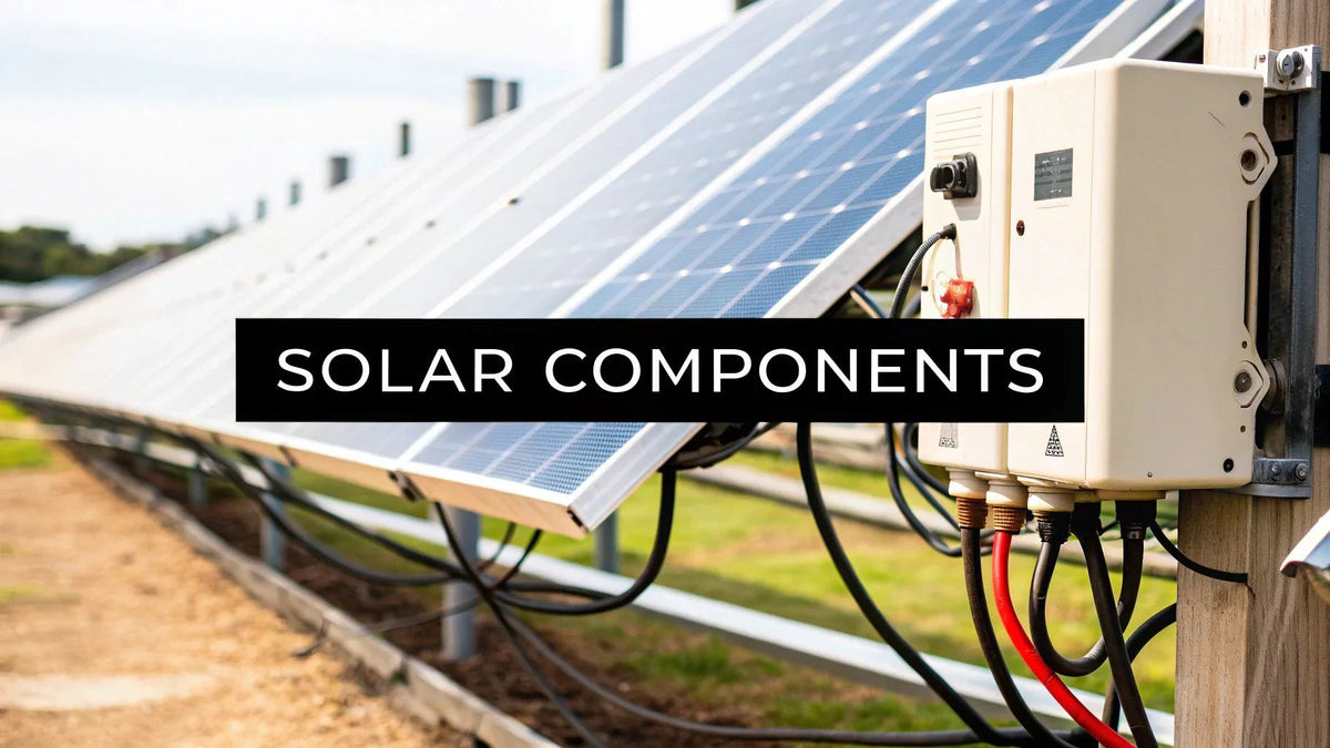
Every solar installer remembers the first system they truly understood — not the first one they assembled, but the first one where every component's job clicked into place as a single machine. The modules stop being "the panels" and become a DC generator with a temperature-dependent voltage curve. The inverter stops being "the box on the wall" and becomes the grid interface that everything else must satisfy. This field manual walks a complete solar panel system component by component, in the order electrons flow, with the specifications, code references, and field habits that separate working systems from warranty claims. It is written for installers sharpening their component knowledge, EPCs training new designers, and serious owners who want to understand what is actually on their roof.
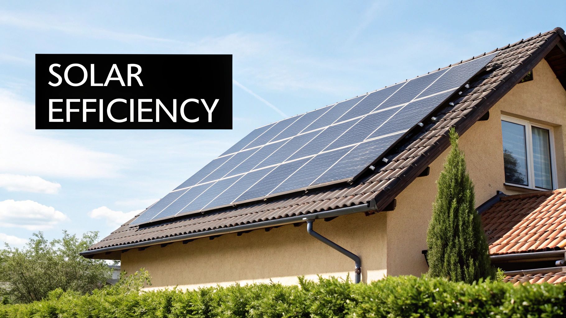
Decoding Your Complete Solar PV System
A grid-tied PV system has five subsystems: generation (modules), power conversion (inverter or module-level electronics), structural (racking), electrical balance of system (wire, overcurrent protection, disconnects, grounding), and metering/monitoring. Storage adds a sixth. The failure pattern we see across thousands of systems is remarkably consistent: components rarely fail alone — they fail at interfaces, or they "fail" because a neighboring component was specified wrong. A perfectly good inverter faulting on a cold morning is usually a string-sizing error. A perfectly good module underproducing is usually a soiling, shading, or connection problem. Understanding the components means understanding what each one demands from its neighbors.
The Real-World Impact of Component Knowledge
This is not academic. The installer who knows that a module's Voc climbs 0.27% per degree of cold does not burn an inverter input on a January morning. The designer who knows the 120% rule does not sell a system the panel cannot legally accept. The owner who knows that one string inverter will need replacement around year twelve budgets for it instead of feeling betrayed by it. Component knowledge compounds across every stage — design, procurement, installation, commissioning, and two decades of ownership — and it is the cheapest performance upgrade available to anyone in this industry. The sections below are organized the way we train: follow the electrons, learn what each box demands from its neighbors, and never trust a compatibility claim that is not in writing.
The Power Duo: Solar Panels and Inverters
Advances in Solar Panel Technology
Current distribution inventory is overwhelmingly monocrystalline: value-tier mono PERC (20–21.5% efficiency) and premium n-type TOPCon and HJT (21.5–23%). The n-type premium buys three things that compound: lower degradation (roughly 0.40%/year versus 0.50–0.55%), better heat behavior (−0.29 to −0.32 %/°C power coefficient versus −0.35 to −0.40), and longer performance warranties (30 years at ~87% retention versus 25 years at ~85%). On space-constrained roofs the premium pays for itself in watts per square foot; on open roofs and ground mounts, value mono delivers more watts per dollar. Bifacial modules earn 5–15% rear-side gain over light-colored ground cover on elevated racking — a free upgrade where the site cooperates. Our panel inventory spans the range, from all-black residential modules to large-format commercial units like the Solar4America 550W class.
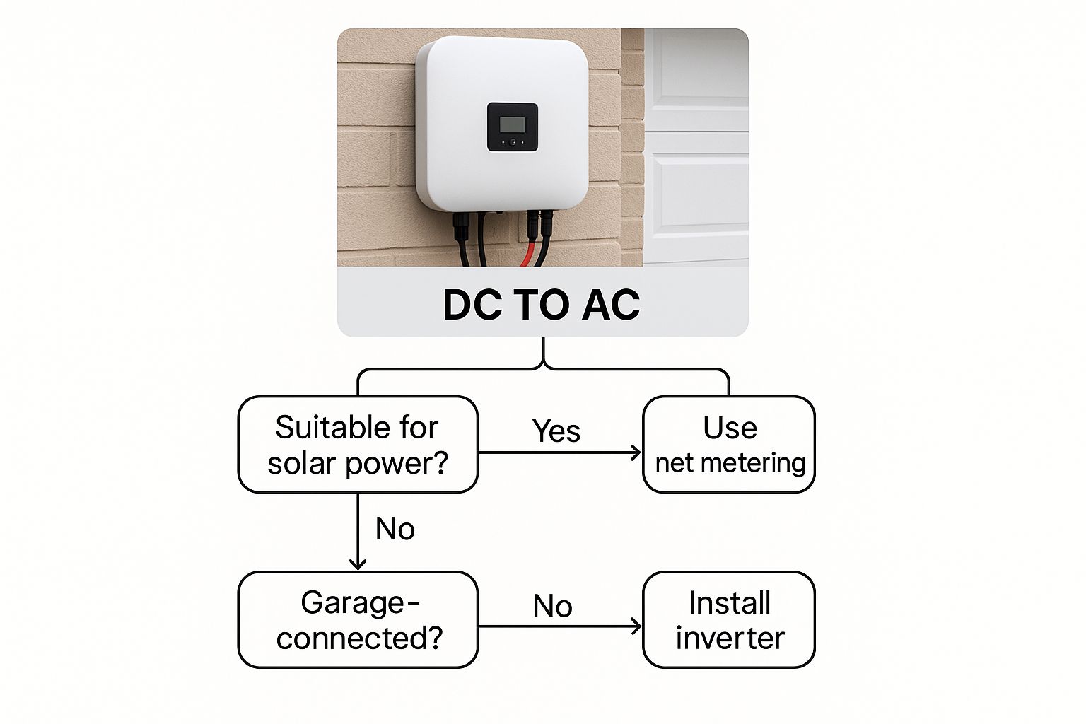
Choosing the Right Inverter Technology
The inverter decision follows three questions in order: Will this system have batteries now or within five years? Is the roof shaded or multi-planed? What does the budget tolerate? The answers map cleanly onto the technology table:
| Inverter Type | Cost Position | Module-Level MPPT | Battery Path | Warranty Norm | Field Notes |
|---|---|---|---|---|---|
| String inverter | Lowest $/W | No (2–4 string MPPTs) | AC-coupled retrofit | 10–12 yrs, extendable | One failure stops everything; mount shaded, garage preferred |
| String + optimizers | +30–50% | Yes | AC-coupled retrofit | 12–25 yrs (optimizer 25) | Module-level data; RSD compliance built in |
| Microinverter | 2–3× string $/W | Yes, native | AC-coupled retrofit | 25 yrs | No high-voltage DC on roof; one failure = one module |
| Hybrid inverter | Premium box, cheap retrofit-avoidance | No (string MPPTs) | Native DC-coupled | 10 yrs | Battery, generator, and backup panel in one ecosystem |
Hybrids like the Sol-Ark SA-8K-48 and the EG4 FlexBOSS21 dominate our battery-certain builds; clean commercial roofs default to string units; complex residential roofs justify micros. The deeper pricing analysis lives in our inverter pricing guide.
Mounting and Racking: The Unsung Heroes
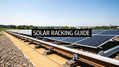
Racking holds the array to the building through thirty years of design loads, bonds every frame into the grounding path, and keeps the roof watertight at every penetration. Rail-based systems forgive uneven structure; rail-less rewards uniform new construction; ballasted trays serve flat commercial roofs; ground mounts buy perfect tilt and easy maintenance with civil work. The full engineering treatment — ASCE 7 wind and snow loads, attachment systems by roof type, torque discipline — lives in our racking guide. The rules that matter on every job: never mix racking brands in one assembly (UL 2703 listings cover tested systems), land every attachment in structural members rather than decking, and torque every clamp to spec — 80–150 in-lb typical for module clamps, verified with a real torque driver and marked with a witness line.
Site Assessment Checklist for Racking Selection
| Check | What to Record | Design Consequence |
|---|---|---|
| Roof structure | Rafter/truss size, spacing, condition from attic | Span table selection; attachment schedule |
| Roof covering & age | Material, layers, remaining life | Attachment type; re-roof-first decision |
| Wind exposure | ASCE 7 design speed, exposure category | Rail spans shrink; edge/corner zones tighten |
| Snow load | Ground snow load, drift zones | Tilt strategy; span reduction; slide-path planning |
| Fire setbacks | AHJ pathway rules (R324.6-class) | Usable roof area drops 20–30% on complex roofs |
| Ground-mount soils | Bearing, frost depth, rock | Driven pile vs. helical vs. ballasted decision |
Balance of System: The Parts That Connect Everything
Wiring and Conduit
PV source circuits run in sunlight-resistant PV wire or USE-2 (90°C wet-rated); home runs in conduit transition to THWN-2. Sizing follows NEC 310.16 ampacity with the 690.8 factor — 1.56 × Isc for source circuits (the double 125%): a 13.1A Isc string needs 20.4A ampacity, which 12 AWG (25A at 75°C) covers before rooftop temperature derating pushes honest designs to 10 AWG. On the AC side, a 7.6kW/240V inverter draws 31.7A continuous, needs 39.6A of ampacity after the 125% continuous factor, and lands on 8 AWG with a 40A breaker from the NEC 240.6 standard sizes. Voltage drop checks run separately from ampacity: target under 2% DC, under 1.5% AC home runs. Our breaker sizing guide covers the OCPD math; the electrical supplies catalog covers the hardware.
Combiner Boxes and Overcurrent Protection
Strings combine where parallel count exceeds one: NEC 690.9 requires string fuses when parallel strings can backfeed more current than a module's max series fuse rating (typically 20–25A) — in practice, three or more parallel strings trigger fusing. Combiner lugs torque to spec (15–25 in-lb on 10 AWG class lugs is typical; read the label), fuse holders get verified with a meter, not a glance, and every combiner gets a directory label. The combiner is also the diagnostic crossroads of the array — per-string clamp readings here identify underperforming strings in minutes, per our output testing guide.
Safety Disconnects and Rapid Shutdown
NEC 690.13–690.17 govern disconnecting means; NEC 690.12 governs rapid shutdown — conductors beyond one foot from the array must drop below 30V within 30 seconds of initiation. On modern rooftops that means module-level electronics: microinverters, optimizers, or dedicated RSD devices, with a labeled initiation device at the service equipment. Verify PVRSS (UL 3741) listing for the specific module-and-electronics pairing; mixing uncertified combinations fails inspections in jurisdictions that check, and fails firefighters in emergencies that matter more.
Grounding, Bonding, and Surge Protection
Every metallic frame and rail bonds to the equipment grounding system (NEC 690.43, Article 250), ideally through UL 2703 integrated bonding hardware used exactly as listed. Surge protection belongs on both sides: an SPD at the AC service protects the inverter and the home; DC-side SPDs protect long string runs and combiners in lightning country. At $200–$500 installed, SPDs are the cheapest insurance in the entire BOM, and Gulf Coast and Front Range installs should treat them as mandatory.
Integrating Energy Storage and Smart Monitoring
The Role of Solar Batteries
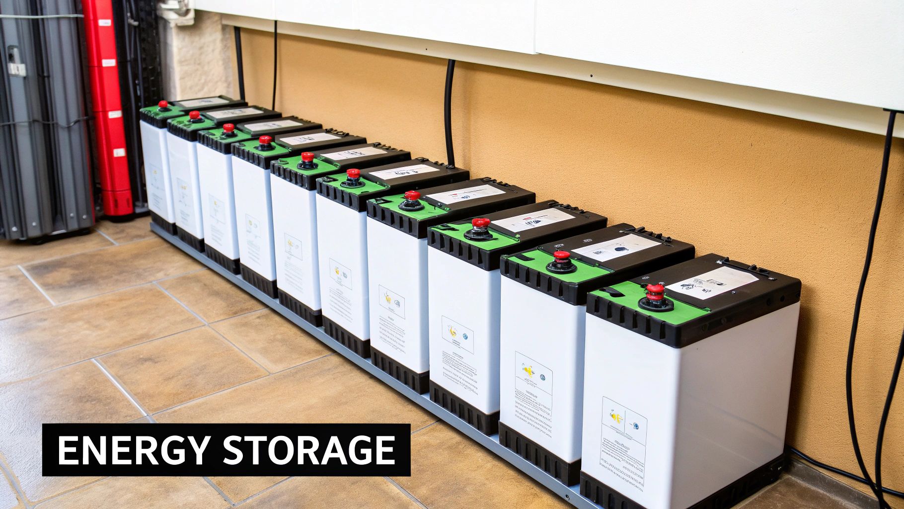
Storage converts a solar system from a bill-reduction device into an energy system. LiFePO4 owns new installs: 80–90% usable depth of discharge, 4,000–6,000 cycles, no maintenance. Modular 5 kWh-class server-rack batteries like the Fortress eFlex Max stack into 10–40 kWh banks; the sizing math (critical loads × autonomy hours ÷ usable DoD ÷ round-trip efficiency) is worked end-to-end in our battery sizing guide. Verify inverter-battery communications compatibility (CAN-bus profile) before purchase — "compatible" means tested and listed, not theoretically possible. And note the code gate: residential lithium ESS above 20 kWh triggers UL 9540 listing and spacing rules in most jurisdictions, which is a design input, not a surprise to discover at inspection.
Smart Monitoring for Performance and O&M
Monitoring is the component that makes every other component accountable. Module-level platforms (micros, optimizers) localize faults to a single panel; string-level monitoring localizes to a circuit. Either way, configure alerts at commissioning: a 10–20% production drop against expected output should generate a ticket, not a shrug. For installers, fleet monitoring converts warranty work from angry calls into scheduled truck rolls. For owners, the monthly glance at the app is the cheapest maintenance ever devised. Revenue-grade metering (ANSI C12.20) matters wherever production has cash value — SREC markets, performance guarantees, PPAs.
Component Lifespan and Replacement Planning
| Component | Expected Life | Warranty Norm | Replacement Reality |
|---|---|---|---|
| Modules | 30–40 yrs (0.4–0.55%/yr degradation) | 12–25 yr product, 25–30 yr performance | Rarely replaced; outlive roofs |
| String inverter | 10–15 yrs | 10–12 yr, extendable to 20–25 | Plan one replacement over system life ($2,500–$4,500 installed) |
| Microinverters | 25+ yrs design | 25 yr | Individual units fail; module-level swap under warranty |
| Racking | Life of structure | 20–25 yr | Essentially never, if torqued and flashed correctly |
| LiFePO4 battery | 10–15 yrs to 80% capacity | 10 yr / throughput-limited | Bank augmentation or replacement mid-system-life |
| Monitoring/comm hardware | 5–10 yrs | 1–5 yr | The weak link; budget one replacement |
| Connectors/wire | 25+ yrs if installed right | — | Failures are workmanship, not age |
The honest reading of that table: budget one inverter and possibly one battery intervention across a 30-year system life, buy warranty coverage that matches those timelines, and keep the documentation that makes warranty claims fast. Our system components guide covers the engineering side of these same decisions.
The Service Panel and Grid Interface
Where solar meets the house, NEC 705.12 writes the rules, and the 120% rule is the one every residential designer memorizes: the main breaker plus the solar backfeed breaker may not exceed 120% of the panel's busbar rating, with the solar breaker at the opposite end of the bus. A 200A bus with a 200A main allows 40A of solar — a 7.6kW inverter at 31.7A fits, an 11.4kW at 47.5A does not. The escape hatches, in cost order: derate the main breaker (200A to 175A frees 65A of backfeed), tap the supply side ahead of the main (governed by service conductor ampacity, not the bus), or upgrade the panel. The panel conversation belongs in the design phase; discovering a 100A panel or a full gutter on install day is how one-day jobs become two-week jobs. Our bus bar capacity guide walks the math with examples.
Off-Grid and Battery-First Variants: How the Stack Changes
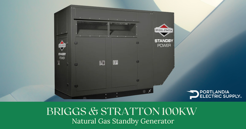
Remove the grid and the component stack reorganizes around the battery. The charge controller appears between array and bank — MPPT only, sized at array watts ÷ battery volts × 1.25, with cold-corrected array Voc under the controller ceiling. The inverter-charger must carry the largest simultaneous load plus motor surge (well pumps and compressors pull 3–5× running watts at start). Battery cables become serious conductors: a 12kW inverter on a 48V bank draws 250A+ continuous, which is 4/0 copper territory under NEC 310.16 with the 125% factor, kept under ten feet because voltage drop at 48V is merciless. And a generator joins the stack as a design component, not an accessory — our off-grid guide sizes the full stack, and the standby generator lineup covers the backup hardware. DC-coupled versus AC-coupled storage is the other architectural fork: DC coupling wins on charge efficiency for new builds; AC coupling wins on retrofit simplicity.
Commissioning and Testing: Where Components Prove Themselves
Assembly is not completion. The commissioning sequence that turns a pile of components into a verified system: torque verification with witness marks on every termination class; insulation-resistance testing on DC home runs before energization; per-string Voc and polarity checks before landing strings (a reversed string at 500V is a lesson learned once); staged energization — AC disconnect, inverter firmware and settings verification, then strings landed one at a time while watching MPPT behavior; and a production baseline recorded against measured irradiance and temperature. That baseline is the reference every future diagnostic depends on — the testing procedures and correction math are laid out in our panel output testing guide. Document everything into the turnover package: photos, serials, settings, baselines. Warranty claims move at the speed of your records.
The Maintenance Reality, Component by Component
Solar is low-maintenance, not no-maintenance, and each component has its own clock:
| Component | Interval | Task | What It Prevents |
|---|---|---|---|
| Modules | Annual (visual); clean as soiling dictates | Inspect for snail trails, delamination, damage; clean in dusty/agricultural zones | 3–7% silent soiling losses; undetected cell damage |
| Inverter | Quarterly glance at monitoring; annual physical | Check error logs, fan operation, heatsink debris, firmware | Thermal derating; missed ground-fault messages |
| Racking & attachments | Annual; after major storms | Witness-mark check on clamps, flashing condition, wire clip integrity | Module slippage; roof leaks; conductor abrasion |
| Combiners & disconnects | Annual | Thermal check under load; torque spot-checks | Resistance heating at loosening lugs |
| Battery (if present) | Monthly monitoring review | SOC trends, temperature, BMS alerts; keep daily cycling in the 20–90% band where configurable | Premature capacity fade — see the 20–80 rule discussion |
| Monitoring hardware | When it stops reporting | Reboot/replace comms gear; verify CT orientation after any electrical work | Flying blind — the costliest maintenance failure is not knowing |
Twenty minutes a quarter and one honest annual inspection keep a system at nameplate performance for decades. The pattern across our service data is blunt: systems with engaged owners and monitoring alerts hold their production curves; unmonitored systems drift, and nobody notices until the true-up bill arrives. For battery-equipped systems, fold the bank into the same rhythm using the battery maintenance guide — storage has its own failure clock, and it runs faster than the array's.
String Sizing: The Ten-Minute Calculation That Prevents Rework
The interface between modules and inverter is a calculation, not a hope. Take eighteen 450W modules — Voc 49.6V, Vmp 41.5V, Isc 11.5A, Voc coefficient −0.27%/°C — into a 1,000V inverter with a 200–800V MPPT window, at a site with a −15°C record low. Cold check: corrected Voc = 49.6 × [1 + 0.0027 × 40] = 55.0V per module, so 18 in series reach 990V — inside the ceiling but with only ten volts of margin, which no designer should accept; run 17 modules or split 9+9 across two MPPTs. Hot check: cell temperatures on a still July roof reach 70°C, dragging Vmp down roughly 13.5% to about 35.9V per module; nine in series deliver 323V, safely above the 200V MPPT floor. Current check: one string at 11.5A Isc needs no fusing; if the design parallels three strings into one MPPT, combined backfeed potential (34.5A) exceeds the typical 20–25A module series-fuse rating and NEC 690.9 fusing applies. Ten minutes of arithmetic, zero change orders. Every failed cold-morning startup and every summer MPPT dropout we have ever diagnosed traces to someone skipping one of these three lines.
Procurement and Compatibility Discipline
Components reach the roof through a supply chain, and the supply chain is where compatibility either gets enforced or gets assumed. The discipline that works: lock exact model numbers and their listings before permit submission (UL 1741 SB for smart inverters, UL 2703 for racking assemblies, UL 9540 for larger ESS, PVRSS certification for rapid-shutdown pairings), batch-match modules to a single production run per roof to avoid color and binning mismatches, and kit every job completely — a missing $40 clamp pack idles a $4,000 crew day. Buy through distribution holding real inventory: quoted lead times are opinions until the pallet has a tracking number. Keep one connector system per project with the manufacturer's crimp die on the truck — cross-mated MC4-compatibles remain the single most common field defect we encounter, and NEC 690.33 prohibits it for good reason. And register warranties inside the manufacturer windows (some require 30–90 days), because an unregistered warranty discovered at claim time is a negotiation you did not plan to have. The installers who run this discipline spend their Fridays on new work; the ones who assume compatibility spend them on rework.
Failure Modes: What Broken Components Teach
Every component class fails in a characteristic way, and knowing the signature saves diagnostic hours. Modules fail slowly (degradation, hotspots from cracked cells, diode failures that cost a third of output) or suddenly (glass breakage, junction-box thermal events) — the slow failures are invisible without baselines. String inverters die from capacitors and fans, concentrated on hot exterior walls; the derating-before-death phase quietly taxes production for months. Microinverters fail individually and politely, one module at a time, which is the architecture's entire economic defense. Connectors and wiring fail at workmanship defects — the cross-mated pair, the uncrimped pin, the conductor abrading on a roof edge — and they fail thermally, meaning they get worse every sunny afternoon. Batteries fade on schedule when kept cool and shallow-cycled, and die young when heat, deep cycling, and below-freezing charging stack up. Monitoring fails silently, which is why it tops the inspection list. The pattern across all of them: failures announce themselves through production data before they announce themselves through hardware. Watch the data and the hardware rarely surprises you.
Designing for the Upgrade You Haven't Planned Yet
The cheapest future-proofing happens at initial install, when walls are open and permits are active. Leave breaker spaces and bus headroom in the panel; the EV charger, the heat pump, and the battery are all more likely than not over a 25-year horizon. Run one extra empty conduit from attic to electrical room while the fishing is easy. Size the inverter for the five-year plan, not the day-one plan — a hybrid bought now is thousands cheaper than a retrofit later. Choose racking and wire management that tolerate a second array section. And keep the documentation package complete, because the crew that expands the system in 2032 will design from your as-builts. None of this adds meaningful cost at install; all of it removes meaningful cost later. The systems that age gracefully were designed by people who assumed the future would show up — it always does.
Common Questions About Solar System Components
What is the typical lifespan of each solar component?
Modules: 30+ years. String inverters: 10–15. Microinverters: 25. Racking: the life of the roof. LiFePO4 storage: 10–15 years to 80% capacity. Monitoring hardware is the weak link at 5–10 years. Plan ownership around those curves and nothing in the system's aging will surprise you.
Can I mix and match brands for different components?
Modules, inverter, and racking from different quality brands: yes, with compatibility verified. Connectors from different manufacturers: never — NEC 690.33 requires mated pairs of the same system. Racking components across brands: never — UL 2703 listings cover tested assemblies. Batteries with inverters: only with verified communications profiles.
What should I consider when upgrading or expanding a system?
Panel capacity first (the 120% rule and breaker space), inverter headroom second, racking compatibility with current module frames third, and utility approval last but not least — expansions typically require interconnection revisions. If batteries are the upgrade, a hybrid-inverter swap during the project is usually cheaper than AC-coupled add-ons; our off-grid and backup guide covers the storage architectures.
Which component should I spend the most on?
The installer's labor and the inverter, in that order. Workmanship determines whether the components get to perform; the inverter determines how the system behaves for its entire life. Modules are commoditized enough that value-tier quality brands deliver most of the watts per dollar; the savings belong in the inverter architecture and the crew.