Every lithium battery that doesn't catch fire has a BMS to thank. That sounds flippant, but after years of selling 48V rack batteries, wall-mounts, and hybrid systems — and seeing a few of the failures when people bypass the protection layer — I've come to think of the battery management system as the actual product. The cells are just the fuel tank. The BMS is the part that watches every cell, every second, deciding what the pack can safely do. When a customer's rack battery refuses to charge on a freezing morning, that's the BMS doing its job. When a bargain no-name pack from an auction site vents in a garage, that's what happens without one.
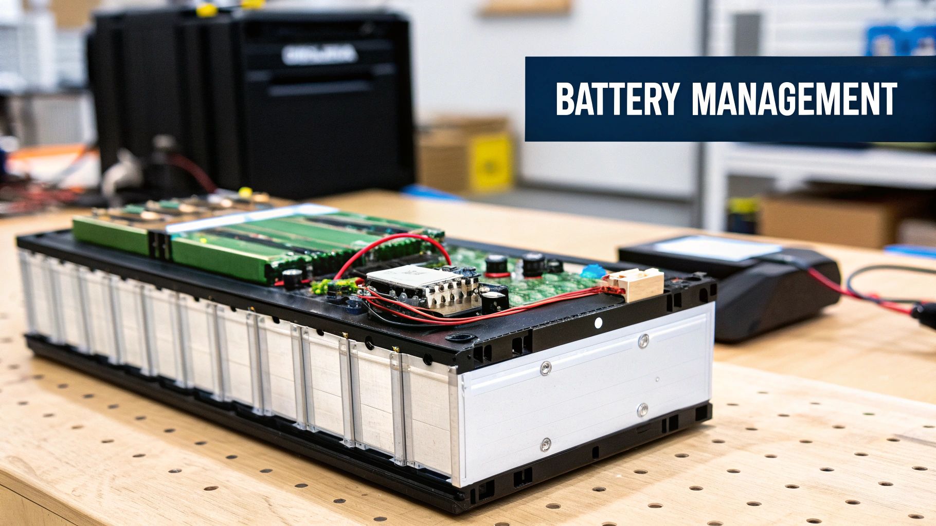
This guide is the working version for installers, EPCs, and developers: what a BMS monitors and protects, how the architectures differ, how to size and select one, which standards actually matter at inspection, and the failure modes we've watched in the field. No vendor fluff — the physics and the code references.
The Core Function: Watch, Decide, Protect
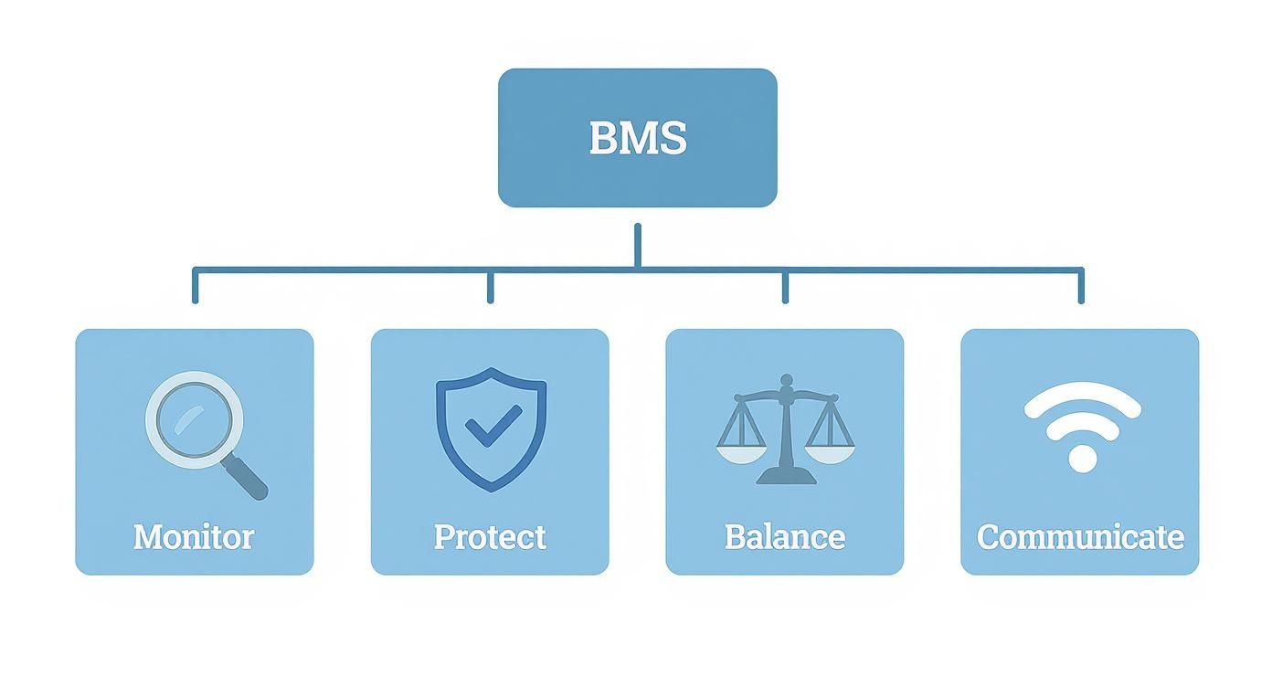
A battery management system is an embedded controller — hardware plus firmware — that sits between the cells and the outside world. Its fundamental loop runs thousands of times per second: measure every cell's voltage, the pack's current, and the temperature at multiple points; compare against programmed limits; and act when anything crosses a line. "Act" means throttling charge or discharge current, opening contactors or a FET switch to disconnect entirely, and reporting everything upstream to the inverter or system controller. The loop never sleeps, never takes a holiday, and never gets to say "close enough" — which is exactly what you want from the only thing standing between a lithium pack and the physics that would otherwise eat it.
Why this matters so much for lithium: lithium-ion cells are unforgiving outside their voltage window, and the window is narrower than most people assume. Overcharge an LFP cell past ~3.65V repeatedly and you plate lithium, grow dendrites, and shorten life dramatically. Overdischarge below ~2.5V and you dissolve the copper current collector — damage that's permanent and invisible until capacity falls off a cliff. Lead-acid tolerated abuse with grace; lithium trades that tolerance for triple the energy density, and the BMS is the price of admission. A lithium pack without a functioning BMS isn't a battery — it's a liability with terminals.
The Four Pillars of BMS Functionality
1. Protection. The non-negotiable layer: over-voltage and under-voltage cutoffs per cell, over-current protection on charge and discharge (with separate, lower limits for charge), over-temperature and under-temperature lockouts, short-circuit protection, and — on heated packs like the ones we stock for cold climates — charge inhibition below 0°C, because charging lithium below freezing plates metallic lithium on the anode. That cold-charge protection is why your customer's battery "won't take a charge" in an unheated garage in January. It's protecting itself from permanent damage.
2. Balancing. Cells in series drift apart — manufacturing variance, temperature gradients across the pack, and self-discharge differences mean no two cells age identically, ever. Without balancing, the weakest cell caps the whole pack's usable capacity. Passive balancing (bleeding excess charge from full cells through resistors, typically at 50–200 mA) is standard on residential packs; active balancing (shuttling charge between cells) shows up on larger and premium systems. Passive works fine when the pack is healthy and gets occasional full charges — which is why the "charge to 100% weekly" recommendation exists for LFP systems that otherwise cycle in the middle band.
3. State estimation. The BMS computes State of Charge (SOC) and State of Health (SOH). LFP's voltage curve is notoriously flat — between 20% and 80% SOC the cell voltage barely moves — so the BMS estimates SOC by coulomb counting (integrating current over time), periodically re-anchoring against voltage at the curve's steep ends. This is why a rack battery's reported SOC drifts if the pack never charges fully, and why a full charge "recalibrates" the gauge. SOH tracks capacity fade against the new-condition baseline; a pack reporting 85% SOH has lost 15% of nameplate capacity.
4. Communication. Modern residential batteries speak CAN bus or RS485 to the inverter using protocols like Pylontech, Growatt, or vendor-specific implementations. Closed-loop communication — where the BMS tells the inverter its real-time current and voltage limits and the inverter obeys — is meaningfully better than open-loop voltage-based charging: charge rates adapt to temperature and cell state automatically, and the inverter stops when the BMS says stop. When we help customers pair batteries and inverters, confirmed closed-loop compatibility is on the checklist before price. The batteries and storage collection and battery buyer's guide track which pairings we've verified, and the sections below explain why this single decision drives more field performance than any cell spec on the sheet.
Chemistry Sets the Limits the BMS Enforces
| Chemistry | Cell voltage range | Nominal | Typical 48V pack config | BMS-relevant traits |
|---|---|---|---|---|
| LiFePO4 (LFP) | 2.5–3.65V | 3.2V | 16S (51.2V nominal) | Thermally stable, flat voltage curve (SOC estimation is hard), no charging below 0°C without heaters |
| NMC | 3.0–4.2V | 3.6–3.7V | 13–14S | Higher energy density, steeper voltage curve (easier SOC), tighter thermal-runaway margins |
| Lead-acid (AGM/Gel) | ~10.8–14.4V per 12V block | 12V | 4 × 12V series | No per-cell monitoring possible; "BMS" is just charge control — one bad block hides until failure |
| Sodium-ion (emerging) | ~1.5–3.9V class | ~3.0V | 17–18S (varies) | Can discharge to near-zero safely; commercial stationary now, residential later this decade |
The lead-acid row explains a lot of field history. A 48V lead-acid bank is four 12V blocks in series with no per-cell visibility — a single sulfated cell drags the whole string, and the only "management" was the charge controller's voltage setpoints. Lithium's per-cell BMS visibility is precisely why LFP banks routinely outlive their warranties while lead-acid banks died young. Our battery chemistry comparison goes deeper on the trade-offs.
Architectures: Centralized, Distributed, Modular
| Architecture | How it's built | Strengths | Weaknesses | Where you see it |
|---|---|---|---|---|
| Centralized | One controller board measures all cells directly | Cheap, simple, compact | Wiring harness grows with cell count; single point of failure | Small packs, 12V/24V drop-ins, most 48V residential rack batteries |
| Distributed | A cell-supervision board per module; a master coordinates | Scales to huge packs; fault isolation per module | Cost and complexity | EV packs, commercial containers |
| Modular | Each battery module has its own complete BMS; modules coordinate as peers | Stack-and-grow capacity; a failed module isolates itself | Coordination overhead; needs a master or brokered arbitration | Stackable residential systems (wall-mount LFP towers), C&I cabinets |
The modular architecture is what changed residential storage forever, and I don't think it gets enough credit. A stack of four 5 kWh modules, each with its own BMS, behaves as one 20 kWh battery to the inverter — and when one module develops a sick cell three years in, the system flags that module, isolates it, and runs degraded rather than dying outright. We've serviced exactly that scenario: customer lost 5 kWh of capacity, got a warranty module, and never had a dark day. With a monolithic pack, the same cell failure means a full pack replacement.
Sizing and Selecting a BMS: The Worked Math
BMS selection reduces to three numbers: series count (voltage), continuous/peak current, and the protection feature set. Worked example — a DIY 48V LFP bank for an off-grid cabin:
| Parameter | Value | Derivation |
|---|---|---|
| Cells | 16 × 280Ah LFP (16S) | 16 × 3.2V = 51.2V nominal "48V" pack |
| Energy | 14.34 kWh | 51.2V × 280Ah = 14,336 Wh |
| Inverter load | 6 kW continuous | Cabin loads + margin |
| Continuous current | ≈117A | 6,000W ÷ 51.2V = 117.2A |
| Surge (motor starts) | ≈234A for seconds | 2× inverter surge rating |
| BMS required | 200A class, 16S LFP profile | 1.7× margin on continuous; surge within peak spec |
| Charge limit needed | ≥100A charge rating | To accept full solar array input at solar noon |
The mistakes in this math that we see weekly: sizing the BMS to the inverter's rating instead of the actual current at pack voltage (117A, not "6 kW / 48V = 125A" — and definitely not "a 100A BMS is close enough," because it isn't); ignoring the charge-side current limit (a BMS that passes 200A discharge but only 100A charge throttles your array); and forgetting that FET-based BMS current ratings assume heatsinking — a 200A BMS in a sealed box with no airflow derates in summer. For pre-built options where this engineering is done — packs with 100A or 200A BMS, heaters, and closed-loop comms — the battery sizing calculator plus our battery storage inventory covers most residential builds, and the EG4 vs. Powerwall comparison shows how the two market philosophies handle BMS design differently.
Standards and Compliance: What the Inspector Wants
| Standard | What it covers | Who needs it |
|---|---|---|
| UL 1973 | Safety of the battery pack itself — including BMS protection functions | Every stationary battery sold for permitted US installs |
| UL 9540 | System-level listing: battery + inverter + BMS as an energy storage system | Effectively required by AHJs for residential ESS permits |
| UL 9540A | Thermal runaway fire propagation test method (a test, not a listing) | Data used by AHJs and fire marshals for large installations |
| IEC 62619 / UN 38.3 | Industrial cell safety / transport safety | Import and shipping compliance |
| NEC Article 706 | Energy storage systems installation rules | Every permitted install |
| NEC 2026 updates | Tightened ESS location, clearance, and labeling rules | Jobs permitted under the 2026 cycle — check your AHJ's adoption |
The practical version: for a permitted residential install, the battery needs UL 1973 and the battery-plus-inverter combination needs UL 9540 listing. Unlisted batteries might work electrically, but the inspector's red tag doesn't care, and neither does the insurance company after a fire. We declined to stock a cheap import line last year for exactly this reason — the cells were fine, the BMS was fine, the paperwork didn't exist. The NEC compliance guide and battery installation guide cover the permitting pathway.
Failure Modes: What We've Actually Seen in the Field
These aren't theoretical. Every one of these has landed on our service bench or in a customer email, most more than once:
- SOC gauge drift. A pack cycled daily between 30% and 70% for months reports fantasy SOC until a full charge re-anchors the coulomb counter. Symptom: "battery says 40%, then dies." Fix: full charge, and set a weekly full-charge schedule.
- Cold-charge lockout confusion. Unheated pack, freezing morning, solar array producing, battery refusing input. Working as designed. Heated packs or indoor placement solve it — the EG4 line and similar heated wall-mounts exist for this.
- Balance failure on one cell group. Pack capacity collapses to the weakest group. Modular systems isolate and warranty-swap; monoliths go back whole.
- Protocol mismatch. Battery and inverter both "support CAN" but speak different dialects; the system runs open-loop, charges conservatively, and nobody understands why performance is mediocre. Verify the exact protocol pairing, not just the connector.
- FET heat failure on undersized BMS. Chronic operation at the current limit, sealed enclosure, August. The BMS dies protecting itself; the customer reads it as a dead battery.
Commissioning Checklist
Commissioning is where BMS quality stops being a datasheet argument and becomes your problem or your pride. Work this checklist on every install, in order, and write the results down:
- Confirm cell count and chemistry profile in the BMS settings match the physical pack.
- Verify closed-loop communication: inverter display shows battery-reported SOC, not estimated voltage-SOC.
- Set charge/discharge limits per the battery datasheet, not the inverter's defaults.
- Test the protections once: low-SOC cutoff behaves as specified; cold lockout if applicable.
- Charge to 100% at commissioning to anchor SOC and run the first balance cycle.
- Document firmware versions on both sides of the CAN bus — future-you, troubleshooting a drift issue in year three, will be grateful.
For deeper system design context, pair this with our BESS design guide, the 80/20 battery rule explainer, and the backup runtime calculator for translating kWh into hours of actual backup.
The 80/20 Rule, Cycle Life, and What the BMS Does With It
LFP cycle life is a direct function of how deep you cycle and where in the voltage band you live. The rough field numbers we quote:
| Cycling pattern | Approx. cycle life (LFP) | Years at 1 cycle/day | Trade-off |
|---|---|---|---|
| 0–100% full cycles | 3,000–4,000 | 8–11 years | Max daily energy, fastest fade |
| 10–90% | 4,500–6,000 | 12–16 years | −20% daily energy, much longer life |
| 20–80% ("80/20 rule") | 6,000–8,000+ | 16–22 years | −40% daily energy, longest life |
The BMS enforces whatever band you configure — most residential systems ship defaulting to roughly 5–95% or 10–90% usable windows, presenting that as "100%" to the user. Two field notes. First, the weekly full-charge exception from earlier still applies: cycle mid-band daily, but let the pack top-balance weekly. Second, size the bank so your normal day fits inside the band you choose — if 80/20 leaves you short every night, the honest fix is more capacity, not deeper cycling. The 80/20 rule explainer walks the trade-off with customer-facing language, and the sizing calculator builds the band into the capacity math.
Thermal Management: The BMS's Hardest Job

Temperature is the variable that kills lithium packs fastest, and it's the hardest to control because cell temperature is uneven by nature — center cells run hotter than edge cells, and the delta grows with current. The BMS manages this with multiple temperature sensors per pack (two to four on residential units, dozens on EV packs), current derating as temperature climbs (a good BMS starts tapering charge current well before the hard cutoff), and heater control on cold-climate models. What it cannot fix is bad installation: a rack battery in direct Arizona sun against a south-facing garage wall will cook regardless of how smart the firmware is. Ambient placement, clearance for airflow, and shade are installer's problems, and NEC 706 location rules plus UL 9540 listing conditions define the envelope. The listings we've seen violated most often: minimum clearance to combustibles and maximum ambient temperature. Both are in the manual; both get ignored; both matter.
Closed-Loop vs. Open-Loop: The Pairing Decision
Since this choice drives more field performance than any battery spec, it deserves the full treatment. In open-loop operation, the inverter charges to fixed voltage setpoints and guesses SOC from voltage — acceptable for lead-acid, crude for LFP's flat curve. In closed-loop, the BMS streams its actual limits to the inverter over CAN: "58.4V absorption, 80A max charge right now, 120A max discharge, cell temps nominal." The inverter obeys in real time. Consequences we've measured: closed-loop systems charge faster on cold mornings (the BMS tapers precisely instead of the inverter guessing conservatively), report accurate SOC, and protect the pack from edge cases open-loop can't see — like one cell group running hot while pack voltage looks fine. When pairing equipment, verify three things: the exact protocol name (not just "CAN"), firmware compatibility on both ends, and that the integration is on the inverter manufacturer's tested list. "Should work" pairs are how commissioning days turn into commissioning weeks.
Reading a BMS Datasheet Without Getting Fooled
The specs that matter, in order: continuous charge and discharge current (separate numbers — a 200A discharge / 100A charge asymmetry is common and throttles solar input at noon); peak current and its duration ("300A peak" means nothing without "for 5 seconds"); balancing current (50 mA passive balancing on a 280Ah cell corrects drift slowly — fine for healthy packs, slow to rescue an imbalanced one); low-temperature charge protection (must exist; heaters preferred in cold climates); and communication protocol (named, versioned, and on your inverter's compatibility list). Specs that mostly don't matter for stationary storage: gravimetric energy density (who cares, it sits on a wall), and cycle-life claims above ~8,000 cycles (laboratory numbers at 25°C that no garage will ever reproduce).
Grid-Scale and Commercial BMS: Same Physics, More Zeros
Commercial and utility storage runs the same four pillars with heavier engineering: distributed architectures with cell-supervision units per module, rack-level controllers, and a site controller above them; thermal management via liquid cooling plates rather than air; and — the big difference — active grid-interactive behavior. A C&I BMS coordinates with the PCS (power conversion system) to deliver frequency response, demand shaving, and ramp-rate control per the interconnection agreement. The procurement guidance matches the residential version, scaled: UL 1973 on the battery, UL 9540 on the system, 9540A test data for the fire marshal, and a named protocol between BMS and PCS that someone has actually commissioned before. For projects in that class, start the conversation with us at the energy storage systems catalog and expect the BMS questions to drive the equipment selection, not follow it.
DIY and Second-Life Packs: The Warning We Give Everyone
The DIY battery community does impressive work, and we sell cells and BMS units to builders who know exactly what they're doing. The failure pattern we warn about: second-life EV modules or auction cells paired with a BMS that's oversized on paper, unconfigured in practice, and never tested for its protection functions. A BMS whose over-voltage cutoff has never been verified is a decoration. If you build: buy the BMS before the cells (its specs define your pack), configure every threshold deliberately, test each protection function once on the bench, and fuse the pack independently of the BMS — FETs fail short, and the fuse is the last honest layer. And for anything grid-connected or permitted, the UL listing conversation above isn't optional, no matter how good the build is.
The Protocol Zoo: A Practical Compatibility Table
CAN bus is the physical layer everyone shares; the protocol dialects are where pairings succeed or fail. The landscape as we deal with it daily:
| Battery ecosystem | Protocol family | Notes from the field |
|---|---|---|
| Pylontech-derived | Pylontech CAN | The de facto open standard; dozens of battery brands and most hybrid inverters speak it |
| EG4 / SOK / many rack batteries | Pylontech-compatible variants | Verify the specific inverter firmware supports the specific battery firmware — "Pylontech protocol" is a family, not a guarantee |
| EG4 closed ecosystem | EG4 native | Tightest integration with EG4 hybrids like the FlexBOSS line — see the FlexBOSS 21 for the current flagship |
| Victron | VE.Can / Lynx BMS ecosystem | Superb documentation and configurability; the off-grid pro's choice, at a price |
| Proprietary (Tesla, Enphase) | Closed | Battery, BMS, and inverter are one engineered system — you buy the integration, you don't build it |
| RS485/Modbus | Legacy and C&I | Still common on commercial PCS integrations and older hybrid gear |
The meta-lesson: an ecosystem decision is a BMS decision. Choose the battery-inverter pairing first as a verified unit, then fall in love with the price. Reverse that order and you'll spend the savings on commissioning labor.
Monitoring, OTA Updates, and the Cloud Question
Modern BMS platforms phone home: cloud dashboards, SOC history, fault logs, and over-the-air firmware updates. The field reality is mostly positive — we've diagnosed customer issues from the desk that used to require a truck roll, and firmware updates have genuinely fixed bugs in the field (one brand's cold-weather charge taper improved noticeably via OTA last winter). But build with eyes open: if the cloud service dies, local operation must continue (every reputable system does — verify it); know where the off switch for remote access is, because some commercial customers' security policies require it; and document firmware versions at commissioning, because "the behavior changed after an update" is a real troubleshooting branch. On the monitoring side, teach the customer one thing: the app is the early-warning system, and a battery that stops reporting deserves a call before it stops working.
Warranties and the BMS Log
Here's something buyers rarely learn until a claim: the BMS log is the warranty record. Cycle count, depth-of-discharge history, temperature excursions, fault events — the manufacturer can read the pack's whole life from it. That's mostly good (claims process faster with data) with one edge: abuse is visible too. A pack that spent a summer at 60°C ambient or got charged below freezing repeatedly shows it in the log, and warranty terms around operating environment get enforced accordingly. Install within the environmental envelope, document the install location, and keep the commissioning record. The pack remembers everything either way. One more wrinkle: keep your own records too — photos of the install clearances, the ambient conditions, the firmware versions. If the manufacturer's copy of the log and yours ever disagree, the party with better documentation wins, and it shouldn't automatically be them.
Cold-Climate Installation: Doing It Right
For unconditioned-space installs in real winter climates, the hierarchy we recommend: heated battery models first (self-heating packs warm themselves from charge or grid power, then accept charge), conditioned-space placement second, insulation-and-heat-tape approaches a distant third. Never defeat the cold-charge lockout — every winter someone asks, and the answer is the same: that lockout is the only thing between the cells and lithium plating, and plating is permanent capacity loss with a side of dendrite risk. In the northern tier we now spec heated packs by default on garage and outbuilding installs; the heater draws 100–300W for an hour on cold mornings and pays for itself in January availability alone.
End of Life: Recycling and Second Life
LFP packs are entering their first big retirement wave, and the BMS matters here too: a pack with intact logs and healthy cell groups is a second-life candidate (stationary reuse at reduced duty); a pack with dead cell groups and no data is recycling feedstock. LFP's lack of cobalt and nickel makes its recycling value lower than NMC's — the economics run on lithium, iron, and copper recovery — so expect take-back programs rather than buy-back prices. What we tell customers: buy from brands with a stated take-back pathway, keep the BMS data intact (don't pull boards for parts), and treat a 15-year-old pack at 70% SOH as an asset with a next job, not waste.
Thermal Runaway: Defense in Depth
Since safety is the whole reason the BMS exists, let's be precise about the failure it guards against. Thermal runaway is a self-heating chain reaction inside a cell: internal heat triggers exothermic reactions that make more heat, and past a threshold the cell vents flammable gas and can ignite. The defense is layered, and the BMS is only layer one: prevention (BMS keeps cells in the safe voltage/current/temperature envelope), detection (temperature and voltage anomaly sensing catches a sick cell before it runs away), containment (pack mechanical design, venting paths, and spacing slow propagation), and system response (contactors open, the system faults offline, and UL 9540A-tested designs demonstrate limited propagation to the AHJ's satisfaction). LFP's chemistry raises the runaway onset temperature substantially versus NMC — one reason it owns residential storage — but "safer chemistry" never means "no protection needed." The cheap packs that make news skip layer one and hope the chemistry covers it. It doesn't.
The BMS Buying Checklist
When a customer or contractor brings us a battery spec sheet to evaluate, this is the exact sequence we run. Confirm the chemistry and cell format first, then the series count and nominal voltage, then the continuous and peak current on both the charge and discharge sides (they're different numbers and both matter), then the balancing method and current, then low-temperature charge protection and whether heaters are included, then the named communication protocol and its presence on your inverter's tested list, then UL 1973 on the pack and UL 9540 on the battery-inverter combination, and only then price per kWh. Any spec sheet that can't answer these eight questions in writing goes back with questions before it goes into a proposal. The brands that answer all eight cheerfully are the brands still answering the phone at year seven of the warranty — the correlation is not subtle. And if the deal involves a "new brand with amazing pricing," apply the Tier 1 logic from our module guides: a battery warranty is a promise about the future, and promises from companies without a balance sheet are marketing copy, not coverage.
Common Questions from Installers and Buyers
What is a battery management system?
An embedded controller — hardware and firmware — that monitors every cell's voltage, current, and temperature in a battery pack; protects against over-charge, over-discharge, over-current, and temperature extremes; balances cells; estimates state of charge and health; and communicates the pack's real-time limits to the inverter. Lithium batteries are unsafe and short-lived without one.
Can I use a lithium battery without a BMS?
No — and any product offering that is a fire risk, not a bargain. LFP cells tolerate no overcharge above ~3.65V or deep discharge below ~2.5V without permanent damage, and no over-current or below-freezing charging without protection. The BMS is what makes lithium's energy density usable.
Why does my battery show wrong state of charge?
Usually SOC drift: LFP's flat voltage curve forces the BMS to estimate charge by counting current, and that estimate drifts when the pack never charges fully. Charge to 100% to re-anchor the gauge, and schedule a weekly full charge if you normally cycle in a mid-band. If drift persists after full charges, check for a failing cell group pulling the estimate off.
What size BMS do I need for a 48V system?
Match series count (16S for LFP "48V" packs) first, then current: continuous amps equal your inverter watts divided by ~51.2V, and the BMS continuous rating should carry at least 1.5× that with surge headroom. A 6 kW inverter on a 51.2V pack draws ~117A — spec a 200A-class BMS, and check the charge-side current limit too.
What's the difference between UL 1973 and UL 9540?
UL 1973 lists the battery pack itself, including its BMS protection functions. UL 9540 lists the complete energy storage system — battery plus inverter plus controls — as an installed unit. Permitted residential installations effectively need both: 1973 on the battery, 9540 on the battery-inverter combination.
Why won't my lithium battery charge in cold weather?
The BMS is blocking charge below freezing to prevent lithium plating, which permanently damages cells. Solutions: a heated battery model that self-warms and then charges, indoor installation, or simply waiting for the pack to warm above 0°C. It's a protection feature, not a defect.