Ask a room of solar installers what killed their worst project and you will rarely hear "the panels." You will hear about the undersized disconnect that failed inspection, the rapid-shutdown transmitter that never talked to the modules, the racking SKU that did not fit the module frame, the battery that would not close CAN-bus with the inverter. Solar systems fail at the interfaces — which means they are designed at the interfaces. Understanding solar energy system components as an integrated whole, rather than a shopping list, is the difference between a BOM that builds and a BOM that generates change orders. This guide walks every major component class with the specs, code references, and compatibility rules we use when kitting real projects.
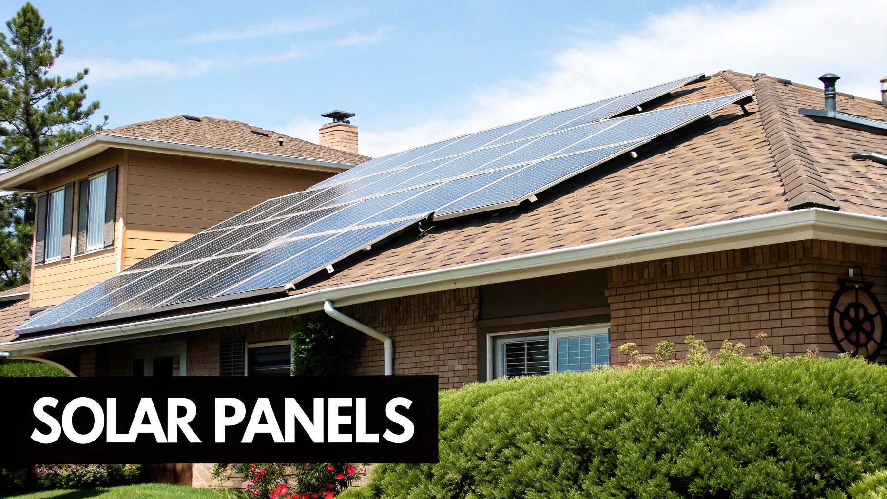
Decoding the Solar Energy Ecosystem
A PV system is a one-way river of energy with five dams: modules convert photons to DC, the inverter converts DC to grid-synchronous AC, the service equipment distributes it, the meter accounts for it, and — increasingly — a battery parks it for later. Every other component exists to protect, connect, or measure that flow. The professional skill is not knowing what each box does; it is knowing how each box constrains the next. Module voltage windows constrain inverter selection. Inverter output current constrains wire, breaker, and panel capacity. Battery chemistry constrains charge control. Racking constrains module choice. We will take them in the order the electrons travel, then circle back for the balance-of-system components that hold it all together.
Solar Panels: The Engine of Your System
Monocrystalline, Polycrystalline, and Thin-Film
Mono PERC won the crystalline war years ago — polycrystalline is effectively extinct in new distribution inventory — and the frontier has moved to n-type architectures: TOPCon and HJT. Thin-film (CdTe, led by First Solar) retains a real niche in utility-scale and hot climates thanks to a superior temperature coefficient, but it is rarely stocked at residential distribution. The practical comparison for today's buyers:
| Technology | Typical Module Efficiency | Power Temp Coefficient | Degradation (Yr 1 / Annual) | Typical Product / Performance Warranty | Best Fit |
|---|---|---|---|---|---|
| Mono PERC (p-type) | 20–21.5% | ≈ −0.34 to −0.40 %/°C | 2% / 0.45–0.55% | 12–15 yr / 25 yr | Value residential and commercial |
| TOPCon (n-type) | 21.5–23% | ≈ −0.29 to −0.32 %/°C | 1% / 0.40% | 15–25 yr / 30 yr | Premium residential, hot climates, space-constrained roofs |
| HJT (n-type) | 21.5–23% | ≈ −0.24 to −0.26 %/°C | 1% / 0.25–0.35% | 15–25 yr / 30 yr | Highest-performance residential |
| Bifacial (PERC or TOPCon) | Front-side rating + 5–20% rear gain | Per base cell type | Per base cell type | 25–30 yr performance | Ground mounts, carports, high-albedo sites |
| Thin-film CdTe | 18–19.7% (utility formats) | ≈ −0.28 %/°C | ~1% / ~0.3–0.5% | 12 yr / 30 yr | Utility scale, extreme heat |
Key Specifications for Professionals
Four datasheet numbers drive system design. Voc and the temperature correction set maximum string length: NEC 690.7 requires correcting module Voc for record-low site temperature using the Table 690.7(A) factors — a string of twelve 49.8V-Voc modules is 597.6V at STC and 669V after a 1.12 correction at −7°C. Vmp/Imp define the operating point the inverter's MPPT must span, hot and cold. Maximum series fuse rating (typically 20–25A) constrains parallel string count before fusing is required per NEC 690.9. And frame height and clamping zones constrain racking compatibility — a detail that has stranded more than one pallet of modules at the jobsite. Our panel catalog spans value mono through premium n-type, from Silfab Elite 370W all-black residential modules to Qcells XL-class commercial formats.
The Rise of Advanced Panel Technologies
Two trends matter for procurement right now. First, n-type's degradation advantage compounds: a TOPCon module warranted at 87.4% at year 30 versus PERC's 84.8% is worth roughly 3% more lifetime energy from the same racking and labor — on space-constrained roofs that is often worth more than the price delta. Second, module formats keep growing; 400W+ residential and 550W+ commercial formats reduce balance-of-system cost per watt but raise handling weight (a 550W large-format module runs 60–70 lbs) and racking compatibility questions. Match the module to the crew and the rack, not just the price list.
Solar Inverters: The Brains of the Operation
The Three Main Flavors of Inverter Technology
| Type | Architecture | Cost Position | Monitoring Granularity | Failure Exposure | Best Application |
|---|---|---|---|---|---|
| String inverter | Centralized DC→AC, 2–4 MPPT inputs typical | Lowest $/W | String-level (module-level with optimizers) | Single point of failure | Unshaded uniform roofs, commercial |
| Microinverter | Per-module DC→AC at the racking | 2–3× string $/W | Module-level native | Distributed — one module drops, rest produce | Complex/shaded residential roofs |
| Hybrid / battery inverter | Solar + battery + transfer + generator in one unit | Premium hardware, avoids retrofit labor | String-level + full energy flow | Single point, but replaces multiple boxes | Any storage-certain or backup-driven project |
Choosing the Right Inverter for the Job
The selection logic runs: storage intent first, shading second, budget third. If batteries are in the five-year plan, a hybrid like the Sol-Ark SA-8K-48 or EG4 FlexBOSS21 bought today beats a string inverter plus tomorrow's retrofit by thousands of dollars. If the roof is chopped into shaded planes, microinverters earn their premium in recovered production. If the roof is clean and the budget is tight, the string inverter remains the rational default — the string inverter lineup and optimizer-based systems like the SolarEdge SE3800H cover this ground. Size by DC:AC ratio (1.2–1.35 residential), verify the cold-corrected string Voc against the input window, and never share an MPPT between roof planes of different orientation.
Advanced Inverters and Grid Compliance
Modern grid-tied inverters are "smart inverters" under IEEE 1547-2018 and UL 1741 SB: they must ride through grid disturbances, regulate volt-var and frequency-watt functions, and accept utility curtailment signals where required. California Rule 21, Hawaii Rule 14H, and an expanding list of utility territories mandate these functions — which is why the inverter on a permit set must be the exact listed model, not an "equivalent." Rapid shutdown under NEC 690.12 is the other compliance pillar: conductors more than one foot from the array must drop below 30V within 30 seconds, which in practice means module-level electronics (micros, optimizers, or RSD transmitters) on virtually every rooftop string system.
Racking and Mounting: The Unsung Hero of Solar
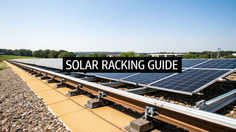
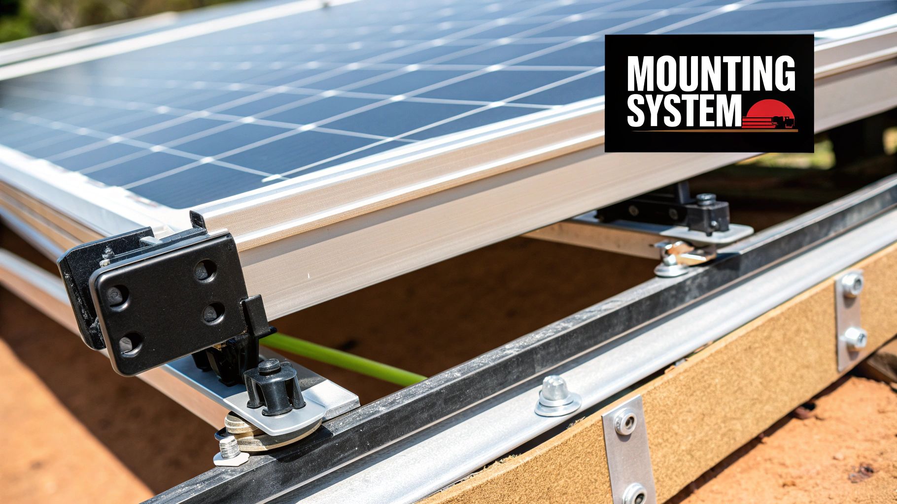
Racking holds the array through thirty years of wind and weather, bonds every frame into the grounding path (NEC 690.43, UL 2703 listed assemblies), and preserves roof integrity at every penetration. Rooftop systems split into rail-based (forgiving, universal) and rail-less (fast, precise); flat commercial roofs go ballasted; ground mounts go driven-pile or helical. The full engineering treatment — wind and snow loads per ASCE 7, attachment by roof type, torque discipline — lives in our solar racking guide. The one rule that survives every project: never mix racking brands in an assembly, because the UL 2703 listing and the engineering letter cover tested combinations only.
Energy Storage and Balance of System Components
The Role of Battery Storage
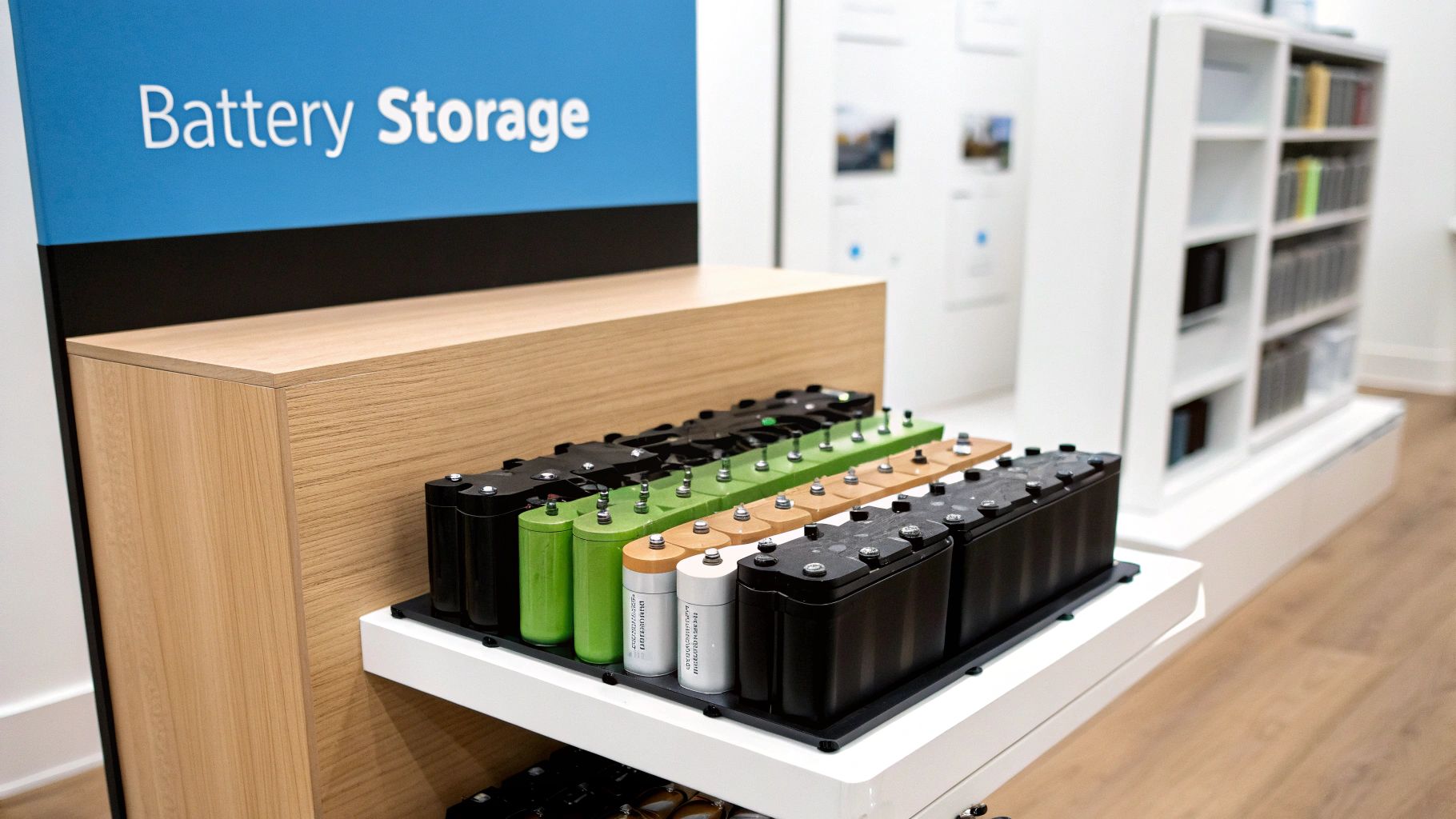
Storage has moved from option to assumption in most new designs. LiFePO4 owns the market — 80–90% usable depth of discharge, 4,000–6,000 cycles, no maintenance — and modular server-rack formats like the Fortress eFlex Max 5.4 kWh let installers scale a bank from 10 kWh to 40+ kWh by stacking listed modules. Sizing follows the critical-loads math: sum the backed-up loads, multiply by the hours of autonomy the customer is buying, divide by usable DoD and round-trip efficiency. Our battery sizing guide runs the numbers; the energy storage collection covers the hardware. One compliance note that bites projects late: lithium ESS above 20 kWh triggers UL 9540 listing and spacing requirements in most jurisdictions — buy listed systems and plan the garage wall layout before the permit set, not after.
Understanding Balance of System Components
BOS is everything that is not a module or inverter — and it is where under-budgeted projects bleed. The critical list:
| BOS Component | Function | Key Code / Spec | Common Field Failure |
|---|---|---|---|
| PV source-circuit wire (USE-2 / PV wire) | Module-to-combiner-to-inverter DC runs | NEC 690.31; 90°C wet-rated, sunlight-resistant | Unsecured conductors abrading on roof edges |
| Connectors (MC4-class) | Module string connections | NEC 690.33 — must be mated pairs of same manufacturer | Cross-mated brands → high resistance, heat, fires |
| Combiner boxes + string fuses | Parallel string aggregation and OCPD | NEC 690.9; fuse when 3+ parallel strings exceed max series fuse rating | Loose lugs — torque to 15–25 in-lb per spec |
| DC and AC disconnects | Isolation for service and emergency | NEC 690.13–690.17 | Underrated disconnects on 1,000V strings |
| Breakers / backfeed protection | Interconnection into service panel | NEC 705.12 — 120% busbar rule | Failed inspection from overloaded bus |
| Rapid shutdown devices | Module-level shutdown initiation | NEC 690.12; PVRSS listing (UL 3741) | Incompatible transmitter/module pairing |
| Surge protection (SPD) | Lightning and switching transient clamping | NEC 690.35 history; good practice on both AC and DC | Skipped entirely — the cheapest insurance in the BOM |
| Monitoring / CTs | Production and consumption metering | Revenue-grade (ANSI C12.20) for SREC markets | CTs installed backwards — reads negative consumption |
The connector row deserves emphasis. Cross-mating MC4-compatible connectors from different manufacturers is the single most common BOS defect we see in the field — the housings click, the contact metallurgy differs, and five years later the joint is a heating element. NEC 690.33 requires mated pairs; UL has flagged the practice for a decade; inspectors increasingly check. Keep one connector system per project, crimped with the manufacturer's die (not pliers, ever), and torqued/verified per spec.
Charge Controllers: The Off-Grid Gatekeeper
Grid-tied systems skip this component entirely; battery systems cannot live without it. The charge controller sits between array and battery, converting array voltage to battery voltage while protecting the bank from overcharge. MPPT (maximum power point tracking) controllers sweep the array's I-V curve continuously and convert the difference — a 150V array charging a 48V bank through MPPT converts voltage headroom into charging current, harvesting up to 30% more than PWM in cold weather when module voltage runs high. PWM controllers, which simply switch the array onto the battery, belong to 12V trickle applications and museums. Sizing: controller amps = array watts ÷ battery voltage, with NEC 690.8's 125% continuous factor, and the array's cold-corrected Voc must stay under the controller's input ceiling. A 3,000W array on a 48V bank needs 3,000 ÷ 48 × 1.25 ≈ 78A — an 80A-class controller like the Victron SmartSolar 250/100 family or MidNite's Classic line. Our controller sizing guide and the controller catalog cover the selection in depth.
Service Equipment and the Grid Interface
The point where solar meets the house panel is the most inspection-scrutinized connection in the system. NEC 705.12 offers several compliant paths: the classic 120% rule (breaker at the opposite end of the bus, PV + main ≤ 120% of bus rating — a 200A panel with a 200A main accepts up to 40A of solar backfeed), supply-side taps ahead of the main breaker (unlimited by the bus, governed by service-entrance conductor ampacity), and main-breaker derates (swap the 200A main for 175A and free 65A of backfeed headroom). The 120% rule fails constantly in older 100A panels and in 200A panels where the solar system grew beyond the original design — the fix hierarchy runs: downsize the main, tap the supply side, or upgrade the panel, in that cost order. Our bus bar guide details the calculation. Generation meters and CTs close the loop: revenue-grade metering (ANSI C12.20 accuracy class) is mandatory in SREC markets and worth specifying anywhere production has cash value.
Monitoring Platforms: The Component Everyone Forgets to Specify
Monitoring ships embedded in the inverter choice, which is exactly why it gets under-specified — it was never evaluated on its own merits. Evaluate it: homeowner-facing apps drive service behavior (an owner who sees production weekly reports faults in days), installer-facing fleet dashboards turn warranty work from reactive to scheduled, and commercial assets need open APIs or Modbus/Sunspec access so third-party O&M platforms can ingest data without a screen-scraping hack. Ask three questions before finalizing any inverter: what does monitoring cost after year five, who owns the data, and what happens if the manufacturer exits the market? We have re-instrumented orphaned fleets; the hardware cost is trivial and the labor is not. Cellular vs. Wi-Fi is its own reliability decision — hardwired Ethernet or cellular beats customer Wi-Fi, which changes passwords and routers without asking anyone's permission.
Conductor Sizing: The NEC Math That Ties It Together
Every wire in the system sizes from the same discipline: ampacity from NEC 310.16 (75°C copper column for terminations), continuous-load factor of 125% (NEC 690.8 for PV source circuits, 210.19 for feeders), and a voltage-drop check. The values we design against daily:
| Copper AWG | Ampacity @ 75°C | Max Continuous (÷1.25) | Typical PV Application |
|---|---|---|---|
| 12 AWG | 25 A | 20 A | Single string home runs (Isc ≤ 15A class) |
| 10 AWG | 35 A | 28 A | Long string runs; small charge-controller outputs |
| 8 AWG | 50 A | 40 A | Paralleled strings; 5–6kW inverter AC at 240V |
| 6 AWG | 65 A | 52 A | 7.6–11.4kW inverter AC output |
| 4 AWG | 85 A | 68 A | Small battery inverter feeds at 48V |
| 2/0 AWG | 175 A | 140 A | 8kW-class 48V battery cables |
| 4/0 AWG | 230 A | 184 A | 12kW-class 48V battery cables |
Worked example: a 7.6kW string inverter at 240V draws 31.7A continuous. NEC 210.19/215 demand 125% → 39.6A → 8 AWG THHN-2 and a 40A two-pole breaker from the NEC 240.6 standard sizes. On the DC side, a string at 13.1A Isc × 1.25 (690.8) × 1.25 (continuous) — note PV source circuits take the double factor, 1.56 × Isc — lands at 20.4A, which 12 AWG covers at 25A ampacity before temperature derating; on hot rooftops with conduit fill, 10 AWG is often the honest answer. The circuit breaker sizing guide walks the OCPD side of this same math.
Commercial-Scale Components: What Changes Above 100kW
Residential component logic scales poorly, and commercial projects add component classes of their own. Three-phase string inverters (50–125kW units at 480V or 800V AC) replace the residential boxes, and medium-voltage transformers step 480V to utility distribution voltage on larger plants — a long-lead item that belongs on the procurement critical path, with 20–40 week lead times not unusual in recent years. DC combiners give way to recombiners, string-level fusing is engineered per NEC 690.9 at scale, and 1,500V string architecture doubles string length versus legacy 1,000V designs, cutting combiner count and trench copper meaningfully. SCADA and DAS (data acquisition systems) replace consumer monitoring, with revenue-grade metering, weather stations, and irradiance sensors feeding availability calculations that the PPA's penalty clauses depend on. The component that surprises residential-to-commercial crossovers most: the O&M spares kit. Specifying one spare inverter per 10–15 units, spare combiner boards, and a documented RMA process at design time is the cheapest availability insurance in the industry.
Commissioning: Where Components Become a System
The difference between components and a system is commissioning, and the difference between a good commissioning and a checkbox exercise is measured data. Our commissioning sequence, the short version: torque verification on every termination class (with witness marks), insulation resistance testing on DC home runs before first energization, Voc and polarity verification per string before landing them in the combiner (a reversed string at 500V is an expensive lesson learned exactly once), then staged energization — AC disconnect closed, inverter commissioned and firmware verified, strings landed one at a time while watching the MPPT behavior. Production baseline: record per-string current and per-module or per-string Voc against measured irradiance and temperature on day one, so year-three diagnostics have a reference. Every step documents into the turnover package the customer keeps — and the package is not bureaucracy for its own sake; it is the document set that wins warranty claims, satisfies insurers, and lets any competent technician pick the system up cold five years from now. The full diagnostic methodology lives in our output testing guide — the same procedures, scaled by system size.
Battery Chemistry: The Four-Way Comparison That Drives Storage Design
Storage selection is a chemistry decision before it is a brand decision. The four chemistries that still appear in real projects, compared on the numbers that size and price them:
| Chemistry | Usable DoD | Cycle Life (to 80%) | Round-Trip Efficiency | Maintenance | $/kWh Installed Position | Best Use |
|---|---|---|---|---|---|---|
| LiFePO4 (LFP) | 80–90% | 4,000–6,000 | 92–96% | None | Baseline | Essentially all new stationary storage |
| Li-ion NMC | 80–90% | 2,000–4,000 | 90–95% | None; stricter thermal management | 10–20% above LFP | Weight/space-constrained (mobile, legacy residential) |
| Sealed AGM | 50% | 500–1,200 | 80–85% | None, but ventilation for fault cases | Cheapest per nameplate kWh, most expensive per delivered kWh | Budget backup, cold standby sites |
| Flooded lead-acid | 50% | 800–1,500 with perfect care | 75–80% | Watering, equalization, venting | Lowest upfront | Hobbyist off-grid where labor is free |
The delivered-kWh math is why LFP won: a 10 kWh AGM bank delivers 5 usable kWh for perhaps 800 cycles — 4,000 lifetime kWh — while a 10 kWh LFP bank delivers 8.5 usable kWh for 5,000 cycles, over 40,000 lifetime kWh. Ten times the lifetime energy for roughly three times the price is not a premium; it is a discount wearing a bigger sticker. NMC survives where volume and weight dominate (its energy density advantage is real) and in legacy product lines. Lead-acid survives where upfront cash is the only metric or where −20°F unconditioned sites punish lithium's low-temperature charge limits. For anything else, our lithium battery inventory and the sizing math in the battery sizing guide are the starting points.
Wire Management and Physical Protection: The Component That Isn't a Component
Ask an inspector what fails solar jobs and wire management ranks with grounding. NEC 690.31(C) requires PV source conductors to be secured and protected — in practice UV-rated clips at 2–4 foot intervals, conductors off the roof membrane entirely, and no cable jackets resting in ponding water or against abrasive edges. PVC-jacketed cable in conduit (THWN-2) belongs in home-run raceways; exposed runs belong in sunlight-resistant PV wire or USE-2. Stainless or UV-stabilized clips, never zip ties on rooftop runs — consumer zip ties are powder in three summers. Critter guards earn their keep anywhere squirrels live: chewed string conductors are a top-five residential service call, and a $150 guard kit is cheaper than one truck roll. The aesthetic dividend is real too — arrays with disciplined wire management photograph like professional work, because they are.
String Sizing: A Complete Worked Example
Tie the module and inverter sections together with one full calculation, because this is the calculation that fails when rushed. Design: eighteen 450W modules, Voc 49.6V, Vmp 41.5V, Imp 10.85A, Isc 11.5A, Voc temp coefficient −0.27%/°C, site record low −15°C, inverter MPPT window 200–800V, max input 1,000V. Maximum string: corrected Voc = 49.6 × [1 + 0.0027 × (25 − (−15))] = 49.6 × 1.108 = 55.0V per module. NEC Table 690.7(A) gives 1.16 at −15°C using the standard table method; the coefficient method is also Code-legal under 690.7(A)(3) engineering supervision in the 2020 NEC — either way, 18 × 55.0 = 990V. That is inside the 1,000V ceiling with ten volts to spare, which is too tight for comfort; drop to 17 modules (935V corrected) or split 9+9 across two MPPTs. Minimum string: hot Vmp — cell temperature on a still, hot roof reaches 70°C, so Vmp falls by roughly 0.30%/°C × 45°C ≈ 13.5% plus degradation: 41.5 × 0.865 ≈ 35.9V, and 9 modules give 323V — comfortably above the 200V floor. Current check: one string at 11.5A Isc needs no fusing; three parallel strings at 34.5A combined exceed a typical 20A max series fuse, so fuse per NEC 690.9. The whole exercise takes ten minutes and prevents the two most common design rework loops we see: cold-Voc over-voltage and hot-Vmp dropout.
The Procurement Lifecycle: From BOM to Spares
Components have a lifecycle beyond install day, and professionals buy with the whole arc in view. At design: lock exact model numbers and their listings (UL 1741 SB, UL 2703, UL 9540 as applicable) before permit submission. At purchase: confirm country-of-origin documentation where IRA domestic content or BABA applies, batch-match modules to a single production run per roof, and kit the job completely — a missing $40 clamp pack idles a $4,000 crew day. At install: photograph serials, register warranties within manufacturer windows (some require registration inside 30–90 days), and file the commissioning baseline. In operation: hold the spares posture we described for commercial work, scaled to residential reality — one spare micro per twenty installed, one RSD transmitter per job class, and firmware versions documented. At end of life: modules and racking recycle through PV-specific recyclers, lithium batteries through certified battery recyclers, and neither belongs in a dumpster — state rules increasingly say so with fines attached.
System Architectures: How the Component Stack Changes by Design
The same component catalog assembles into three meaningfully different machines. A straight grid-tied system is the minimal stack: modules, racking, RSD electronics, inverter, and interconnection hardware. Every omitted component is a feature — fewer parts, fewer failure points, lowest cost per watt. A hybrid system adds the battery bank, a critical-loads subpanel (and its feeder, breaker, and relocation labor — budget $800–$1,500 in electrical work for the subpanel alone), consumption CTs, and usually a generator input. The critical-loads panel is the component homeowners never see coming: moving twelve circuits is a half-day of licensed labor that has to be in the quote or it becomes an awkward conversation. A full off-grid stack adds charge controllers (on component-architecture builds), a generator with automatic-start integration, and heavier DC infrastructure — 2/0 to 4/0 battery cables, Class T fusing within seven inches of the battery per ABYC-influenced practice that NEC 480/706 installations echo, and battery enclosures with working clearances. Our off-grid systems guide sizes that full stack end to end.
Component Stack Comparison by System Type
| Component Class | Grid-Tied | Hybrid / Backup | Off-Grid |
|---|---|---|---|
| Modules + racking | Required | Required | Required, typically oversized 20–40% |
| Inverter | String or micro | Hybrid inverter-charger | Off-grid inverter-charger or hybrid |
| Battery bank | None | 10–40 kWh typical | 1–3 days of autonomy |
| Charge controllers | None | None (integrated MPPTs) | Required on component builds |
| Critical-loads subpanel | None | Required | Usually the whole panel |
| Generator + AGS | Rare | Optional | Standard |
| Rapid shutdown | Required on roofs (NEC 690.12) | Required on roofs | Required on roofs; ground mounts often exempt |
| Transfer equipment | None | Integrated ATS or microgrid interconnect device | Generator transfer built into inverter |
Grounding, Bonding, and Lightning Protection
Grounding is the component discipline nobody markets and every inspector checks. NEC 690.41–47 plus Article 250 govern: module frames and racking bond into the equipment grounding conductor (integrated-bonding clamps under UL 2703 make this automatic when used as listed), inverter and battery chassis land on the EGC system, and a grounding electrode conductor ties the new equipment to the premises electrode system. The field errors are consistent: a bonding lug landed on painted steel without a listed scrape-or-pierce method, EGCs sized from habit instead of NEC 250.122, and ground-mount arrays missing their own electrode where the structure qualifies. Lightning protection is a separate decision: a full NFPA 780 lightning protection system is overkill for most homes, but SPDs on both the AC service and, for long DC runs, the DC side convert most surge events from equipment losses into non-events. In lightning-prone regions — Florida, the Gulf Coast, the Front Range — we treat SPDs as mandatory line items, and the $200–$500 they cost has saved our customers five figures in inverters and appliances over the years.
Module Reliability: What Field Data Actually Shows
Module marketing emphasizes efficiency; module economics are actually driven by reliability, and the field data tells a consistent story. Modern crystalline modules fail in the field at rates well under 0.5% per year for reputable manufacturers, and the dominant failure modes are unglamorous: junction-box failures (heat and potting defects), backsheet degradation (a specific wave of polyamide backsheets from the mid-2010s cracked industry-wide — a cautionary tale about novel materials), diode failures, and interconnect ribbon corrosion in hot-humid climates. Glass breakage from handling and hail is logistics, not manufacturing. The procurement translation: buy from manufacturers with balance sheets that can honor a 25-year warranty, demand IEC 61215/61730 certification as table stakes, and look at PVEL or equivalent independent reliability scorecards when they cover your candidate. A module 0.5% more efficient that fails twice as often is a bad trade at any price. Warranty claims process through whoever holds the relationship — one more reason installer supply chains matter to homeowners, and one more reason we stock deep on the module lines we stand behind in the panel catalog, from Mission Solar and JA Solar through REC and Qcells.
Emerging Components Worth Watching
Three component classes are moving from edge cases to line items. Bidirectional EV charging hardware turns the vehicle into a 60–100 kWh battery on wheels; UL 9741-listed bidirectional chargers and vehicle-to-home capable EVs are real products now, and designs that provision for them (panel capacity, charger location, utility approval path) will age well. Smart electrical panels and circuit-level load managers increasingly replace the dumb critical-loads subpanel, shedding and prioritizing loads dynamically during outages — a 10 kWh battery with intelligent load management rides through outages that defeat a 15 kWh bank without it. Module-level power electronics keep consolidating: the rapid-shutdown transmitter, the optimizer, and the monitoring node are collapsing into single devices, which simplifies rooftops and BOMs alike. None of these belong in every design today — but all three belong in every designer's vocabulary this year. Every designer should know where the puck is moving, because the panel schedule and conduit stubs you install this year decide whether the 2030 upgrade is an afternoon or a rebuild. Our standing advice to installers: whenever a wall is open or a trench is dug, drop one extra empty conduit and leave spare breaker spaces. The materials cost less than lunch; the retrofit they prevent costs thousands, and customers remember the contractor who made their future upgrades easy.
Putting It All Together for Optimal Performance
The Component Interdependency Checklist
Before any BOM leaves our warehouse, it survives this checklist. Run yours the same way:
- Module cold-corrected string Voc < inverter max input voltage, at the site's record low, using NEC 690.7(A) factors
- Module hot Vmp > inverter MPPT minimum at the site's record high cell temperature
- Parallel string count ≤ max series fuse math, or string fuses specified
- Module frame height and clamping zones compatible with the racking system's listing
- Inverter AC output × 1.25 ≤ breaker and conductor ampacity; backfeed ≤ NEC 705.12 panel allowance
- Battery chemistry and BMS protocol listed on the inverter's compatibility sheet (CAN/RS485 verified, not assumed)
- RSD transmitters listed with the specific module/inverter pairing (PVRSS certification)
- One connector system throughout, with the matching crimp die on the truck
- Rapid-shutdown initiation device labeled per NEC 690.56(C)
Finalizing a Resilient and Profitable System
The checklist looks like overkill until the first time it saves you. We run it because every line is scar tissue: the inverter that would not wake on a cold morning (line one), the battery that refused to close its contactor until a firmware patch (line six), the RSD pairing that passed inspection in one county and failed in the next (line seven). Component knowledge is not trivia. It is the difference between a system that is merely installed and a system that is engineered. For testing and commissioning discipline once everything is landed, our panel output testing guide picks up where this one ends.
Common Questions About Solar System Components
What is the most important component in a solar energy system?
The inverter, by a wide margin in terms of failure frequency, feature content, and design leverage — it is the only component that touches every watt. But the honest engineering answer is "the interfaces": module-to-racking, connector-to-connector, battery-to-inverter. Systems fail at boundaries, and professionals design boundaries first.
Can I mix and match brands for different components?
Yes, with discipline. Modules, inverters, and racking from different quality brands coexist fine when the compatibility checklist above is honored. What you cannot mix: connectors (same manufacturer mated pairs only), racking assemblies (UL 2703 listing applies to the tested system), and batteries with inverters lacking a verified communications profile.
What is the typical lifespan of each solar component?
Modules: 30+ years with 0.25–0.55% annual degradation. String inverters: 10–15 years (warranty extensions to 20–25 are cheap insurance). Microinverters: designed and warranted for 25. Racking: the life of the roof or longer. LiFePO4 batteries: 10–15 years to 80% capacity at moderate cycling. Monitoring hardware: the weak link — plan on one replacement in the system's life.
How do component choices affect my permits?
Directly. Permit sets list exact models: the smart-inverter listing (UL 1741 SB) for interconnection, the PVRSS certification for rapid shutdown, UL 9540 for larger battery systems, the racking engineering letter for structural review. Swapping "equivalent" hardware after plan approval means resubmittal in most jurisdictions — lock the BOM before the permit package goes in.
Where do projects most often overspend on components?
Premium modules on unconstrained roofs (space is free — buy value watts), oversized inverters at 1.0:1 ratios, and duplicated monitoring hardware. Underspend traps: skipping surge protection, cheaping out on connectors and wire management, and buying unlisted battery equipment that cannot pass inspection.