Nobody thinks about the junction box until one fails, and then it is the only thing anybody thinks about. I have diagnosed more dead strings than I can count, and after the obvious suspects — a tripped breaker, a fried optimizer, a squirrel with expensive taste — the trail ends at that little plastic enclosure glued to the module backsheet more often than the industry likes to admit. This guide covers what a solar panel junction box actually does, how to read its ratings, how it fails in the field, and what installers and EPCs should specify so it never becomes the reason a crane comes back to a finished array.
The junction box is the electrical handshake between the module's internal cell strings and the rest of your system. Everything that makes a module safe and serviceable — bypass diodes, output terminals, cable glands, the potting that keeps weather out — lives in a box smaller than a deck of cards that must survive 25 years of thermal cycling, UV, and whatever the local wildlife considers edible.
Anatomy: what is inside the box
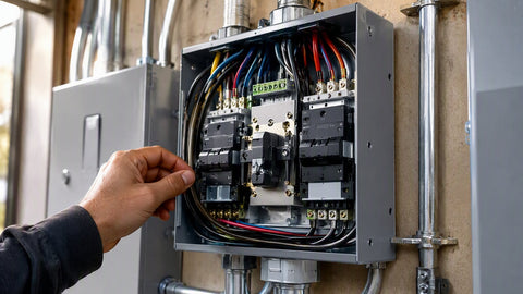
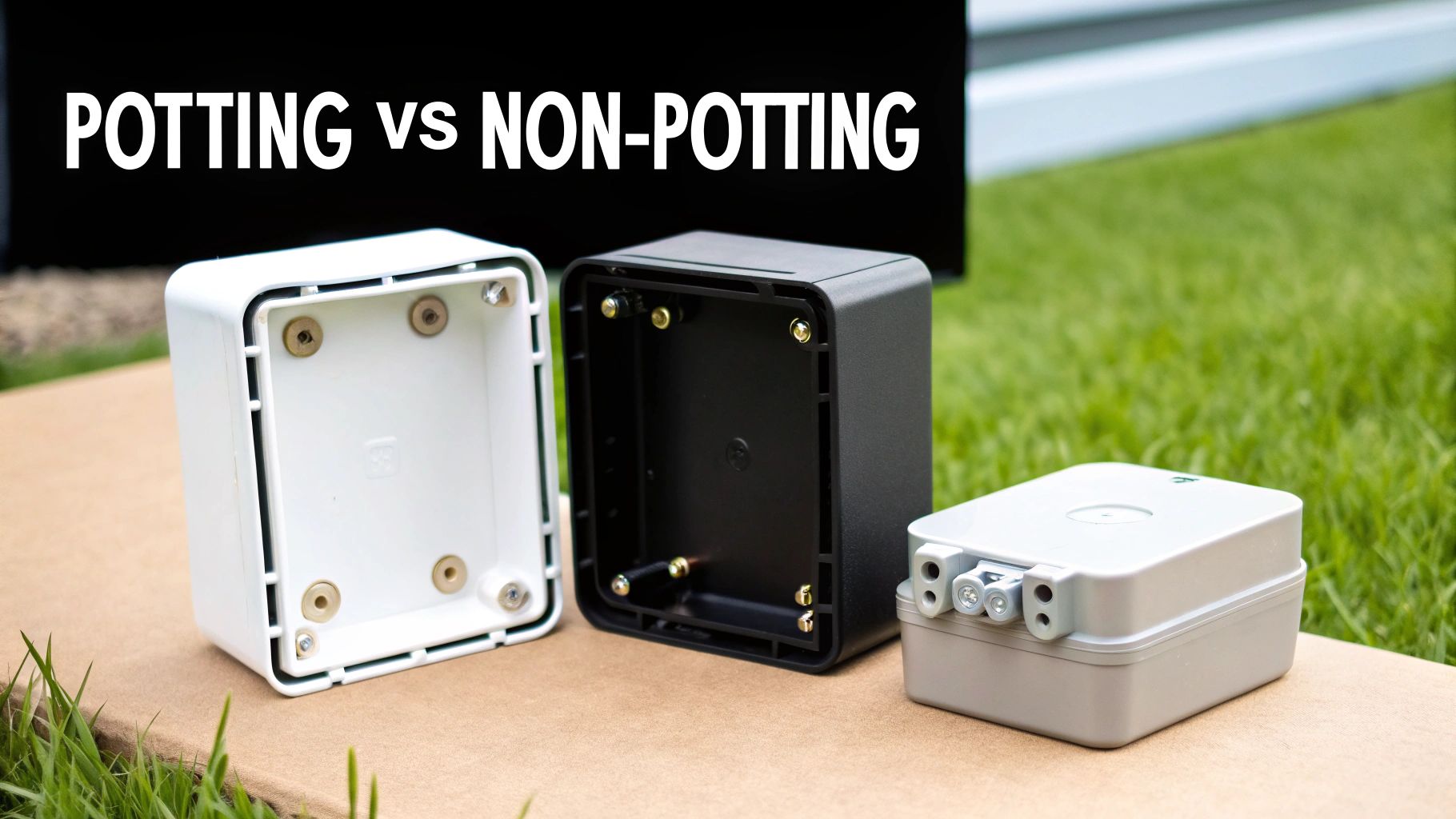
Open a quality junction box (on a dead string, with gloves, after verifying absence of voltage) and you will find four functional elements. First, the terminal strips or welded foils that land the cell-string ribbons from the laminate. Second, the bypass diodes — usually three on a standard 72-cell-format module, one per cell substring. Third, the output cables with their connectors, factory-crimped and strain-relieved through cable glands. Fourth, the potting or sealing system, which is either a full silicone potting compound or a gasket-and-vent design depending on the manufacturer.
Each element has a failure signature, and learning to read them turns diagnosis from guesswork into pattern recognition. A discolored terminal means resistance heating from a poor ribbon bond. A box lid bowed outward means the potting expanded under heat — often a diode that has been working too hard. Melted cable gland threads mean the connector pair was cross-mated or the crimp was marginal from day one.
IP ratings: the two digits that decide survival
Junction boxes carry IEC 60529 ingress protection ratings, and the digits are not marketing — they are test protocols. The first digit is solids, the second is liquids. For rooftop modules you will almost exclusively see IP65, IP67, or IP68:
| Rating | Solids protection | Liquids protection | Field meaning for PV |
|---|---|---|---|
| IP65 | Dust-tight | Low-pressure water jets from any direction | Acceptable for pitched roofs with good drainage; marginal for flat-roof ponding zones |
| IP67 | Dust-tight | Temporary immersion, 30 min at 1 m | The practical standard for quality residential and commercial modules |
| IP68 | Dust-tight | Continuous immersion under manufacturer-specified pressure/time | Spec worth paying for on flat commercial roofs, carports, and coastal jobs |
| Below IP65 | Varies | Spray only or less | Walk away — not a serious outdoor PV rating |
The rating applies to the assembled box with its lid and glands intact. The moment a field technician re-terminates a cable without re-sealing the gland to torque, the IP rating is a historical document. This is why module manufacturers universally void warranties over opened boxes, and why the correct field repair for a failed box is almost always module warranty replacement rather than box surgery.
Bypass diodes: the hardest-working part nobody specs
Bypass diodes exist for one reason: shade. When a cell substring is shaded, it stops producing and starts consuming — the unshaded cells drive current backward through the shaded cells, which dissipate it as heat. Unchecked, that hot spot can exceed 150°C and permanently degrade the laminate. The bypass diode across each substring conducts around the shaded section, sacrificing one-third of the module's output to save the module.
Reading a diode spec sheet requires three numbers:
| Parameter | Typical modern value | Why it matters |
|---|---|---|
| Type | Schottky (axial or SMD) | Low forward voltage means less self-heating while bypassing |
| Forward voltage drop (Vf) | ≈ 0.4–0.55 V at rated current | Every 0.1 V of Vf at 10 A is a watt of heat inside the box |
| Average forward current (If) | 15–30 A class | Must exceed the module's Isc with margin — a 14 A module on a 15 A diode has no headroom |
| Peak reverse voltage (Vr) | 45–200 V class | Must exceed the open-circuit voltage the substring can impress across the diode |
| Junction temperature rating | Typically 200°C rated, real-world target well below | Ambient box temperature on a dark roof can exceed 70°C before the diode does any work |
The field reality: a diode that spends every afternoon bypassing a chimney shadow is a diode aging fast. Diode failures usually fail short — the substring goes permanently bypassed and the module loses a third of its voltage. You find it with a Voc check: a 72-cell module that should read ~45 V reading ~30 V has one shorted diode; reading ~15 V has two. That Voc test takes ninety seconds and is the single highest-value diagnostic on a residential service call.
How junction boxes fail: the field catalog
After enough warranty seasons, the failure modes sort themselves into a short list:
| Failure mode | Symptom in monitoring | Root cause | Correct response |
|---|---|---|---|
| Shorted bypass diode | Module or string voltage ~33% or ~66% low | Chronic shading, undersized diode, thermal runaway | Module warranty claim; fix the shade source |
| Open diode | Hot-spot heating under shade; possible cell damage | Diode cracked from thermal cycling or surge | Warranty claim; check for lightning history |
| Terminal corrosion | Intermittent string dropout, worse in damp weather | Compromised seal, condensation cycling | Document for warranty; do not re-seal in the field |
| Delaminated box adhesive | Box visibly lifting from backsheet | Bad adhesive batch, backsheet contamination at factory | Warranty claim — this is a manufacturing defect, full stop |
| Connector overheating | Burnt smell, discolored connector pair | Cross-mated connector brands, field-crimped connectors | Replace pair with matched, listed connectors per 690.33 |
| Box cracking / lid loss | Visible damage, moisture ingress | Impact, hail, or UV-degraded polymer on old modules | Module replacement; check hail rating of replacement |
The thermal math installers should be able to do
Here is the calculation I make apprentices run before they are allowed to dismiss a junction-box temperature complaint. A module on a dark comp roof at 35°C ambient runs cells at roughly 60–65°C. The junction box, smaller and pressed against warm laminate, sits near cell temperature. Now engage one bypass diode carrying 10 A at 0.5 V forward drop: that is 5 W dissipated inside a box with maybe 15 cm² of external surface. Without meaningful heatsinking, diode junction temperature climbs 40–80°C above the box ambient — you are now at 100–145°C at the die, adjacent to backsheet polymers rated for continuous service around 105–120°C depending on formulation. Run that condition five hours a day through a summer and you understand why "the chimney only shades it a little" is not the reassurance the customer thinks it is.
The design takeaway is boring and absolute: design shade out of the array, or use module-level power electronics that eliminate the hard-bypass condition entirely. The wiring basics guide covers how series strings propagate one module's shade problem across the whole string's output.
Connectors and the cross-mating problem
NEC 690.33 is blunt: connectors must be listed for the application and mated as matched pairs from the same manufacturer, same product line. "MC4-compatible" is not a listing — it is a marketing phrase describing a shape. Stäubli's position, and the code's, is that mixing connector brands creates a pair whose contact resistance, pull-out force, and sealing have never been tested together. I have pulled apart cross-mated pairs that measured triple the contact resistance of a matched pair. At 12 A continuous, that is real heat at the exact spot the installer cannot see from the ground.
Field crimping deserves the same suspicion. A proper factory crimp is made with calibrated tooling on specified wire. A field crimp with a $25 die-less tool is a resistor waiting for a hot day. Where field extension is genuinely unavoidable, use listed crimp tooling matched to the connector line, pull-test every crimp, and record it in the commissioning photos. Our PV wire guide covers the cable side of that junction.
What listing actually means: UL 1703, UL 61730, and the junction box
Modules sold for code-compliant US installation carry listing to UL 61730 (which superseded UL 1703) or IEC 61730 equivalence through a NRTL. The junction box is evaluated as part of that listing: its materials, creepage and clearance distances, potting adhesion, and diode thermal performance are all inside the certification envelope. This is why swapping a junction box — or even re-terminating its cables with unlisted parts — voids more than the module warranty; it technically invalidates the listing the AHJ relied on at inspection. The serviceable path is always the manufacturer's warranty channel. Document with photos, Voc readings, and monitoring history, and let the module maker own its hardware.
For the balance of the circuit outside the box, the usual rules apply: conductors sized per NEC 310.16 with 690.8 multipliers (see our ampacity guide), overcurrent protection per 690.9 where parallel strings require it, and surge protection where lightning exposure justifies it — the SPD guide covers that selection.
Diagnosis workflow: from alarm to answer in one ladder trip
When monitoring flags an underproducing string, run this sequence before you schedule a second visit. At the inverter or combiner, check string Voc against the design value corrected for temperature — a full string at expected Voc with low current points at shade or soiling; a string at two-thirds Voc points at a diode. Compare string currents on the same MPPT with a DC clamp meter; a 30 percent spread between twins is a finding, not a rounding error. Then the ladder: visual on every box for bowing, discoloration, lifted adhesive, and connector condition; an IR camera pass if you have one, where a working bypass diode shows as a localized hot rectangle against the module's backsheet and a failing cell shows as a round hot spot. Ninety percent of junction-box diagnoses complete with these four checks and one photograph set.
Procurement notes for EPCs and fleet buyers
Buying modules at scale means the junction box becomes a line-item risk decision. Three questions separate durable product from future warranty overhead. First, what is the diode current rating relative to module Isc — you want 1.25× minimum, and 1.5× on modules headed for shade-prone residential fleets. Second, what IP rating and potting approach does the box carry, and does the manufacturer publish thermal-cycling data behind it. Third, what connectors ship from the factory, and will the factory crimp your specified jumper lengths so your crews never field-crimp at all. Manufacturers in our 400–459W residential tier and 550–709W commercial tier differ meaningfully on all three, and our counter staff can pull datasheets side by side — that comparison has killed more than one purchase order, correctly.
Field notes: the box that taught me humility
Early in my career I condemned an entire 24-module string as a combiner fault because the voltages looked impossible. Two hours and one very patient senior tech later, we found a single module with two shorted diodes dragging the string's behavior sideways — a $0 problem in parts and a full lesson in diagnostics. I have since watched the same movie on other people's roofs: always test the modules before you condemn the electronics. We keep a laminated diode-Voc reference card in every service van for exactly this reason, and it has paid for the laminating pouch a thousand times over.
Split boxes, edge boxes, and why module architecture moved
Older modules carried one center-mounted box the size of a cigarette pack. Modern large-format modules almost universally use a split architecture: three small boxes spread across the module's width, one per substring, connected by a flat conductor under the laminate. The split design does three jobs at once — it shortens the internal ribbon runs, it puts each diode physically adjacent to the substring it protects, and it lets the module sit nearly flush on rails without a center hump fighting the racking. Edge-mounted boxes on glass-glass and bifacial modules take the concept further, moving the entire junction off the active back surface so rear-side light collection is unobstructed. If you are comparing modules for a bifacial carport, box placement is a real spec — a fat center box shadows rear cells all afternoon. Our bifacial panel selection shows how the major manufacturers solve it differently.
Creepage, clearance, and the physics of staying un-arc'd
Inside every listed junction box, conductive parts maintain two minimum distances: clearance (through air) and creepage (along surfaces). At the 1,000 V and 1,500 V system voltages common in commercial work, those distances are not suggestions — surface contamination from humidity cycling turns inadequate creepage into a tracking path, and tracking becomes an arc, and an arc inside a polymer box becomes the photographs nobody wants on their insurance claim. This is why potting exists: a fully potted box replaces the air and surface geometry with a solid dielectric, shrinking required distances and sealing out the contamination that starts tracking in the first place. When you see a discount module with an unusually small box claiming a 1,500 V rating, that geometry question is exactly what the UL evaluation exists to answer — and exactly why unlisted product has no place on a permitted job.
What the test standards actually put a box through
IEC 61215 and UL 61730 qualification is not a paperwork exercise. The box endures thermal cycling — hundreds of cycles between deep cold and 85°C-class heat — followed by damp heat at 85°C and 85 percent relative humidity for 1,000 hours, followed by humidity-freeze cycles that try to pump moisture past every seal. Bypass diode thermal testing runs the diodes at rated current while measuring junction temperature rise. Adhesion testing tries to peel the box off the backsheet. A module family that passes earns its listing; the modules that fail these tests do not get sold at reputable supply houses, full stop. This is the quiet value of buying through a distributor who verifies listing documents instead of a marketplace seller who cannot spell NRTL.
Spec-sheet red flags our counter staff check
| Spec-sheet item | Good sign | Red flag |
|---|---|---|
| Junction box IP rating | IP67 or IP68 stated explicitly | No rating stated, or "water resistant" marketing language |
| Bypass diode current | Rated ≥ 1.25× module Isc | Diode rating absent from datasheet entirely |
| Connector brand | Named, listed manufacturer (e.g., genuine Stäubli MC4 family) | "MC4 compatible" with no brand, or mixed brands on positive vs negative |
| Cable gauge and length | 4 mm² / 12 AWG class, lengths stated | Unusually thin cable or lengths that force field extensions |
| Certifications | UL 61730 listing with a named NRTL | CE mark alone (a self-declaration, not a US listing) |
| Module warranty terms | 25-year product warranty including box and diodes | Warranty carving out "electrical accessories" or labor |
The economics of a junction-box service call
Run the numbers once and you will never skip the design-stage shade conversation again. A residential truck roll to diagnose a suspected diode failure costs a service company $250–$450 fully burdened — ladder time, testing, documentation. The module warranty covers the hardware, but unless the original contract assigns it, the labor conversation with the homeowner is awkward every single time. Commercial arrays multiply the problem: accessing a box on a carport or a high-pitch industrial roof can require a lift rental that exceeds the module's value. The installers who protect themselves do it in writing at contract time — workmanship warranty terms that state plainly who pays for manufacturer-defect access labor — and in design, by treating chronic partial shade as a problem to engineer out, not a condition to diode around. The racking overview includes the layout levers that move modules out of shade paths in the first place.
Junction boxes meet module-level power electronics

Optimizers and microinverters change the junction-box story rather than deleting it. An optimizer-cabled module still carries its factory box and diodes — the MLPE manages the string-level behavior, while the diodes still protect substrings from hard shade inside the laminate. On microinverter systems the module leads land directly on the trunk-cabled unit, and the box's role narrows to substring protection only. Either way, the box remains the module's listed interface, and the warranty logic is unchanged. For designers weighing string versus MLPE architectures, our inverter fundamentals article and the current inverter picks frame that fork with the hardware we actually stock, including the hybrid units that dominate our residential orders now.
Storage-side cousin: battery and inverter junction practice
Everything that makes module boxes fail — moisture, thermal cycling, marginal crimps, mismatched connectors — applies double to battery and inverter DC junctions, where currents run three to five times higher. A 10 kW hybrid inverter pulling 200+ A from a 48 V battery bank turns a resistive lug into a space heater. Use listed lugs, torque to the datasheet with a calibrated wrench, apply antioxidant where the lug manufacturer specifies it, and protect the whole run with correctly rated OCPD — our BMS and protection collection and the battery bank sizing guide cover the storage side of junction discipline. The 48V battery lineup is where most of those systems start.
Field notes: teaching the Voc test to a new hire
We have answered the same phone call a hundred times: "the string is low, is the inverter bad?" Nine times out of ten the inverter is innocent. I make every new hire run the full sequence on a training array before their first solo service call — design Voc math at current cell temperature, meter verification, the two-thirds rule for diode counts, the clamp-meter spread check. The ones who learn it stop swapping inverters that were never broken. The ones who guess generate warranty claims against perfectly good electronics and eventually confess. There is no shame in the laminated card. There is shame in the third unnecessary truck roll.
A worked shading example: what the diodes actually cost you
Take a 10-module residential string of 400 W modules, Vmp 37.5 V each — 375 V nominal at the inverter input. A vent pipe shades one-third of one module every afternoon. Without diodes, that shaded substring acts like a resistor and can drag string output down disproportionately while cooking itself. With healthy bypass diodes, the shaded substring bypasses: the module contributes two-thirds voltage, string Vmp drops to about 362.5 V, and the string loses roughly one-third of one module's power — call it 3.3 percent of string output during the shaded hours. That is the good outcome, and it still costs real kWh across a summer. The bad outcomes stack when the diode itself fails: a shorted diode locks that third away permanently, shade or no shade, and an open diode removes the protection entirely, returning you to hot-spot physics. Design the shade away and none of this math is ever load-bearing.
Repowering older arrays: box condition tells the truth
On repowering jobs — replacing 15-year-old modules on structurally sound racking — the old junction boxes are the best diagnostic record on the roof. UV-chalked box housings, brittle cable jackets near the glands, and green corrosion at terminal screws tell you the array lived hard; clean boxes with supple cables usually mean the modules still have years in them and the underperformance complaint is elsewhere, usually at the inverter. We advise customers honestly here: if the boxes look tired, the backsheet and encapsulant are aging on the same schedule, and piecemeal module swapping chases a moving target. A full repower with modern 460–549W modules on the existing rails frequently produces 40 percent more energy from the same roof and resets the warranty clock for another quarter century.
Warranty documentation that manufacturers actually accept
File the claim correctly the first time and it sails; file it sloppy and it circles for months. The package that works: module serial number photos, the installed-array photo showing module position, Voc and (if accessible) Isc readings with ambient and estimated cell temperatures noted, monitoring exports showing the underproduction window, and the original proof of purchase. Claim reviewers are engineers reading fifty of these a week — give them numbers with units and they say yes fast. Give them "string seems low" and you will be pen-pals for a quarter. Our system components guide is a decent refresher for the office staff who often shepherd these claims.
Hail, cold, and the Pacific Northwest reality check
Our region is gentle on boxes compared to hail alley, but the two failure accelerators we do have are moss-zone moisture and gorge wind. Persistent damp rewards every marginal seal, and winter wind events flex large-format modules enough to work adhesive bonds that were marginal from the factory. After the big February windstorm season, add a box-condition walk to any service route in exposed areas — five minutes with binoculars from the ground catches lifted lids before the spring rains find them. Cheap insurance, and the customer thinks you are clairvoyant.
Installer best practices that keep boxes out of trouble
Most junction-box longevity is decided during installation, not at the factory. Wire management is first: box cables must be clipped to the racking with listed UV-rated clips so no lead rests on the roof surface or dangles where wind can work it — a swinging lead fatigues the gland seal one gust at a time, and a lead lying on hot asphalt shingle is cooking its jacket every August. Drip loops matter more than apprentices think; water follows a taut cable straight into a gland, and the loop is what makes it let go. Connector pairs should be fully seated until the latch clicks audibly, then tug-tested, then clipped so the pair is not bearing the cable's weight. And the golden rule of service: never open a module box in the field, no matter how confident the diagnosis. The moment the lid comes off, the warranty conversation ends and the liability conversation begins.
Pair those habits with sound electrical design — conductors from our heavy-gauge wire selection where feeders demand it, raceways chosen per the conduit types guide, and grounding per the NEC 690.43 bonding guide — and the junction box goes back to being what it should be: the most boring component on the roof, doing its job silently for thirty years.
The takeaway for specifiers
Spec the box like it matters, because on a 25-year asset it does: IP67 minimum, diode headroom of 1.25× Isc or better, named listed connectors, factory-crimped leads, and a manufacturer whose warranty desk answers email. Then install it like it matters: clipped leads, drip loops, matched connector pairs, and zero field surgery. Do those two things and the junction box returns to its natural state — invisible, sealed, and silent, converting a quarter century of weather into nothing more than a line item on a datasheet that turned out to be true.
One honest closing note from the warranty desk: the junction box failures we see are overwhelmingly concentrated in two populations — very old modules approaching end of life, and very cheap modules that should never have been on a truck. The broad middle of the market, listed product from manufacturers with real US warranty support, almost never generates a box claim when the installation was clean. Buy the middle, install it carefully, and spend your diagnostic energy on the inverters, where the failures that actually interrupt production tend to live.
Spec it right, install it clean, document everything — and the box you never think about will never give you a reason to.
That is the whole craft of it, learned one dead string at a time across twenty years of Northwest rooftops.
Frequently asked questions
What does a solar panel junction box do? It houses the connections between the module's internal cell strings and the output cables, and it holds the bypass diodes that route current around shaded cell sections. It is the module's electrical interface to the rest of the system, sealed to an IP rating for outdoor survival.
Can a solar panel junction box be repaired or replaced? In practice, no — not in the field. The box is sealed and evaluated as part of the module's UL listing, so opening it voids both the listing and the warranty. The correct path for a failed box is a manufacturer warranty claim and module replacement.
How do I know if a bypass diode has failed? Measure the module's open-circuit voltage. A 72-cell-format module reading roughly two-thirds of expected Voc has one shorted diode; one-third means two. Monitoring systems flag the same condition as a chronically low string voltage.
What IP rating should a solar junction box have? IP67 is the practical standard for quality modules. IP65 is acceptable on well-drained pitched roofs, and IP68 is worth specifying on flat commercial roofs, carports, and coastal installations where water exposure is persistent.
Are MC4 connectors from different brands compatible? No, not per code. NEC 690.33 requires connectors to be listed and mated as matched pairs from the same manufacturer. Cross-mated "MC4-compatible" connectors have never been tested together and are a documented overheating risk.
How long should a junction box last? It is designed to outlive the module's 25-year product warranty. Real-world failures cluster in high-shade applications that overwork the bypass diodes and in early-production modules with adhesive or potting defects — which is what the warranty channel exists for.