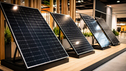
Most solar array failures I have traced in the field come down to one of three things: a loose MC4 connection that cooked itself over two summers, a grounding mistake that back-fed fault current into the inverter, or a combiner box wired with the wrong polarity on a string. These are not exotic failures — they are installation errors, and they are preventable. This guide covers the practical wiring of solar panels for installers, electricians, and serious DIYers: series versus parallel, wire gauge selection, MC4 best practices, combiner box wiring, grounding per NEC 690, and rapid shutdown compliance. If you need panels first, browse our solar panel catalog or residential starter kits.

Wiring a full system? Pair this guide with our charge controllers and inverters for a complete design.
In series, panel voltages add while current stays constant. In parallel, currents add while voltage stays constant. The choice is not arbitrary — it is driven by the charge controller or inverter input window and the shading environment. A string of ten 40V panels in series gives 400V, which a string inverter or 600V charge controller handles easily. The same ten panels in parallel would give 400V still (voltage doesn't add in parallel), but 100A of current — far beyond what most controllers accept.
| Wiring Method | Voltage | Current | Best For | Shade Impact |
|---|---|---|---|---|
| Series | Adds (V1+V2+V3...) | Constant (lowest panel) | String inverters, MPPT controllers with high V input | One shaded panel kills entire string current |
| Parallel | Constant (single panel V) | Adds (I1+I2+I3...) | PWM controllers, low-voltage battery systems | Shaded panel only affects its own branch |
| Series-Parallel | Adds per series group | Adds per parallel group | Large arrays, optimizing V and I for equipment | Shaded string kills that string only |
Last fall I troubleshot a residential array in Gresham where the homeowner had wired fourteen 370W panels all in parallel into a single Victron 150/70 MPPT. The controller was seeing 41V and 53A — the voltage was too low for efficient MPPT operation, and the current was above the 70A limit. The fix was simple: rewire into two strings of seven, giving 287V and 26A per string, well within the controller's 150V/70A window. The array output jumped 18% the same afternoon.
Solar DC circuits run at lower voltage than household AC, which means higher current for the same power — and higher current means more voltage drop and more heat. NEC 690.8 requires PV circuit ampacity to be sized at 125% of Isc (short-circuit current) before temperature correction. Then NEC 310.16 gives you the base ampacity, which you must correct for rooftop temperature (add 17°C to ambient for roofs within 36 inches of roof deck) and conduit fill.
| PV Wire Gauge | Max Ampacity (90°C, free air) | Typical Use | Max Run (3% drop, 10A, 48V) |
|---|---|---|---|
| 14 AWG PV | 35A | Small arrays, single panel jumpers | ~45 ft |
| 12 AWG PV | 40A | Residential strings up to 15A | ~70 ft |
| 10 AWG PV | 55A | Standard residential strings, 15–30A | ~110 ft |
| 8 AWG PV | 75A | Large strings, long homeruns | ~175 ft |
| 6 AWG PV | 95A | Combiner-to-controller, battery interconnects | ~280 ft |
For rooftop arrays, the wire between the junction box and the first combiner is usually #10 or #12 PV wire — it's UV-rated, double-insulated, and designed for 90°C wet/dry. Below the roof, transition to THHN in conduit for the run to the inverter or charge controller. Never use standard NM-B (Romex) for DC solar circuits — it is not rated for the voltage or the temperature. We've found melted Romex in three attic runs where homeowners tried to save money; all three were fire hazards.
| Conductor | Temp Rating | UV Rated | Approved For | NEC Reference |
|---|---|---|---|---|
| PV Wire (RHW-2) | 90°C wet/dry | Yes | Exposed rooftop DC circuits | NEC 690.31(C) |
| USE-2 | 90°C wet/dry | Yes | Underground or exposed DC circuits | NEC 690.31(C) |
| THWN-2 | 90°C wet/dry | No | Conduit runs indoors/outdoors | NEC 310.104 |
| XHHW-2 | 90°C wet/dry | No | Conduit runs, larger conductors | NEC 310.104 |
| NM-B (Romex) | 60°C | No | NOT APPROVED for PV circuits | NEC 690.31(B) |
MC4 connectors are the standard for PV module interconnections, and they are deceptively simple: strip, crimp, click. But a bad crimp is the leading cause of DC arc faults in residential solar. Here's the field process we use:
- Strip length matters: 7–8 mm of exposed conductor, no more. Too long and the metal pin doesn't seat fully; too short and the spring contact doesn't grip.
- Use a proper MC4 crimp tool: The $15 Amazon specials work once, then the die opens up and you get loose crimps. Buy the Stäubli or Multi-Contact branded tool — it's $80–$120 and pays for itself on the first callback you avoid.
- Crimp, then tug-test: After crimping, pull the conductor with 10 lbs of force. If it moves, cut it off and do it again.
- Never disconnect under load: MC4s are not load-break rated. Open-circuit the string at the combiner first, then disconnect the MC4s. Disconnecting a 400V string under load will arc, and the arc can weld the contacts.
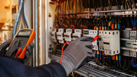
- Check polarity before clicking: Reverse polarity on a string inverter will blow the fuse or damage the input stage. Use a multimeter on every string before connecting to the combiner.
We've replaced at least a dozen MC4s over the years where the installer used diagonal cutters to strip the wire, nicking the copper and creating a high-resistance point that heated to 180°F on hot days. Use a proper wire stripper with the correct gauge slot.
Combiner Box Wiring: Fuses, Busbars, and Grounding

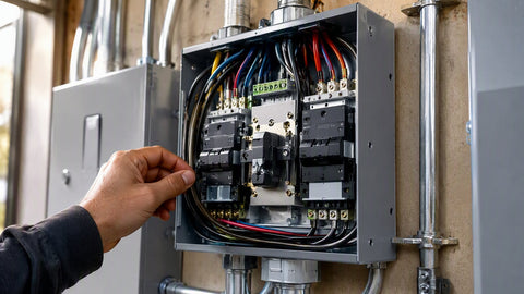
The combiner box is where parallel strings come together before heading to the charge controller or inverter. Every string gets its own fuse or breaker — NEC 690.9(A) requires overcurrent protection for each parallel source circuit. A typical residential combiner might have four strings, each fused at 15A, feeding a single 6 AWG homerun to the inverter.
| String Isc (STC) | Fuse Size (125% × Isc) | Max Strings per Combiner | Homerun Gauge | Typical Controller |
|---|---|---|---|---|
| 9.5A | 15A | 4 strings (60A total) | 8 AWG | Victron 150/70 |
| 10.2A | 15A | 4 strings (60A total) | 8 AWG | Victron 150/70 |
| 11.5A | 20A | 3 strings (60A total) | 8 AWG | Victron 150/70 |
| 13.8A | 20A | 3 strings (60A total) | 6 AWG | MidNite Classic 150 |
| 15.2A | 25A | 2 strings (50A total) | 6 AWG | MidNite Classic 150 |
Inside the combiner: negative busbar for all string negatives, fused positive busbar for all string positives, and a grounded equipment busbar bonded to the enclosure. The equipment ground connects to the array racking ground, which connects to the premises grounding electrode system per NEC 690.47. Do not use the negative conductor as the equipment ground — that's a code violation and a shock hazard.
Every exposed metal part of the PV system — frames, racking, combiner boxes, conduit — must be bonded to equipment ground. NEC 690.47 gives three methods: connection to the premises grounding electrode system, a separate ground ring, or a ground rod at the array. In practice:
- Roof-mounted residential: Bond the racking to the premises ground via #6 AWG copper (or #4 aluminum) run inside metallic conduit. Use WEEB clips or lay-in lugs on every rail section — a single ground bolt at one end of the array is not enough.
- Ground-mount: Drive a ground rod at the array and bond it to the premises ground with #6 AWG copper. The array rod is supplemental — it does not replace the premises electrode.
- Tracker mounts: Use flexible grounding jumpers at every pivot point. A rigid ground wire will fatigue and break within two years of tracker motion.
The array equipment ground is separate from the system grounding conductor (the DC negative reference). In an ungrounded system (most modern string inverters), the DC conductors float and the equipment ground provides the only fault-current path. In a negatively grounded battery system (common with PWM controllers), the negative DC conductor is bonded to ground at one point only — usually the charge controller or battery negative bus. Multiple neutral-ground bonds create ground loops and stray current corrosion.
NEC 690.12 requires that PV systems on buildings have a rapid shutdown function that reduces voltage to 30V or less within 10 seconds of activation, measured within 10 feet of the array. For 2026, this applies to all new rooftop installations and most retrofits. Two compliant approaches:
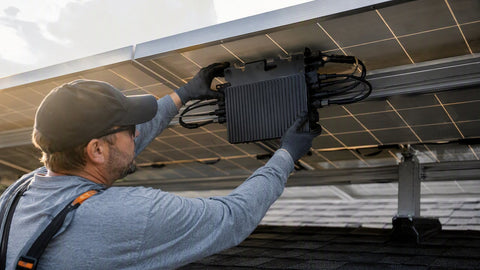
- Module-level power electronics (MLPE): Enphase microinverters or SolarEdge power optimizers shut down each module individually when AC power is lost. This is the simplest compliance path — no extra wiring, no extra switches. The module output drops to near-zero within seconds of grid loss or breaker opening.
- String-level rapid shutdown devices (RSD): A transmitter in the inverter or a separate control box sends a keep-alive signal over the DC conductors. When the signal stops, RSD switches at the array cut the strings. The array side of the RSD drops to 30V; the inverter side sees full string voltage until the inverter discharges its capacitors.
Field note: RSD switches fail more often than MLPE. In the past three years, we've replaced four string-level RSD units that stuck closed or failed to transmit, leaving the array energized during an emergency. Microinverters and optimizers have had zero rapid-shutdown failures in our installed base. If the budget allows, MLPE is the more reliable compliance path.
Plan the string layout
Check the inverter or controller input voltage window. Size strings so that Voc at record low temperature stays below the max input, and Vmp at high temperature stays above the minimum MPPT voltage. Use the manufacturer's string sizing tool — every major inverter maker has one.
Install racking and grounding
Mount rails, attach WEEB clips or lay-in lugs, and run the equipment ground bond wire before placing modules. It's much easier to ground an empty rail than one covered with panels.
Place modules and connect strings
Start at the end farthest from the combiner. Connect panels in series using factory MC4 leads or custom-made jumpers. Check polarity at every third panel with a multimeter — catching a reverse-polarity string at the combiner saves hours.
Home-run to combiner
Use #10 AWG PV wire for string homeruns under 100 feet. Transition to THHN in EMT below the roof deck. Label every conductor at both ends — "String A1, String A2" — and record the layout on the as-built drawing.
Land in combiner and test
Install string fuses, connect to busbars, and verify open-circuit voltage on every string before closing the combiner output breaker. A 10% voltage variance between strings of the same module type indicates a wiring error or a shaded/damaged panel.
Commission and monitor
Power up the inverter or controller, verify MPPT tracking, and record baseline production data. Set up remote monitoring if available — Enphase Enlighten, SolarEdge Monitoring, or Victron VRM. Hand the homeowner the monitoring login and the as-built diagram.
Field takeaway: Size strings for the equipment voltage window, use proper MC4 crimps, never disconnect under load, ground every rail, and verify polarity at every step. A half-hour of multimeter checking during install saves a full day of troubleshooting later. For backup power integration, pair your solar array with a hybrid inverter and battery storage.
Can I mix different wattage panels in the same string?
Only if they have the same voltage profile (Vmp and Voc within 5%). Mixing a 37V panel with a 41V panel in series forces the lower-voltage panel to operate at the higher voltage, which drops its current and can create hot spots. In parallel, mismatched voltages cause reverse current flow through the lower-voltage panel. Best practice: identical modules per string, identical strings per combiner.
How far can I run PV wire from the array to the inverter?
Distance is limited by voltage drop, not by an absolute maximum. For a 400V string, 3% drop allows roughly 350 feet of #10 AWG. For a 48V battery-direct array, 3% drop limits #10 AWG to about 45 feet. When in doubt, upsize the wire — the cost of thicker copper is far less than the production loss from voltage drop.
Do I need a disconnect between the array and the inverter?
Yes — NEC 690.15 requires a disconnecting means within sight of the inverter. For string inverters, this is usually a DC disconnect switch or breaker in the combiner. For microinverters, the AC breaker in the main panel serves as the disconnect. The rapid shutdown device does not satisfy the disconnect requirement unless it is also listed as a disconnecting means.
Can I use aluminum wire for solar DC circuits?
Aluminum is permitted by NEC 690.31 but is rarely used below 4/0 AWG because termination compatibility and oxidation issues make it unreliable for small-gauge DC connections. Copper is the standard for residential and light-commercial solar. If you use aluminum, you must use connectors rated for AL-CU transition and apply antioxidant compound at every termination.
What happens if I wire a string backwards?
Reverse polarity on a string inverter will typically blow the string fuse or DC breaker. On some inverters, it can damage the input diodes — a $500–$1,500 repair. On a charge controller, reverse polarity can destroy the input stage entirely. Always verify polarity with a multimeter before connecting to any equipment.
How do I wire panels for a 24V battery bank?
Use two 60-cell or 72-cell panels in series (80–90V), which gives enough voltage for an MPPT controller to efficiently down-convert to 24V while staying below the 150V input limit of most controllers. A single panel at 40V into a 24V battery is too low for efficient MPPT operation — you'll lose 15–20% of potential harvest.
Is conduit required for rooftop PV wire?
PV wire (RHW-2) is rated for exposed outdoor use, so conduit is not strictly required for the rooftop jumpers between panels. However, most AHJs require conduit for the transition through the roof deck, for runs below the roof, and for any wire within 10 feet of the ground. EMT is standard for exposed runs; PVC Schedule 40 is acceptable underground. Always check local amendments.
- Solar Panels — 300W to 700W modules for residential and commercial
- Charge Controllers — MPPT and PWM controllers for every voltage
- Inverters — string, micro, and hybrid inverters
- Battery Storage — lithium and lead-acid banks
- Residential Solar Starter Kits — pre-engineered systems
- Off-Grid Cabin Kits — complete remote power packages
Ready to wire your array? Get a Quote — we'll spec the panels, wire, and balance of system for your roof or ground mount.