Last Updated: 2026 • Field-reviewed by the PES Supply counter team • NEC references: 690.8, 690.33, 310.16
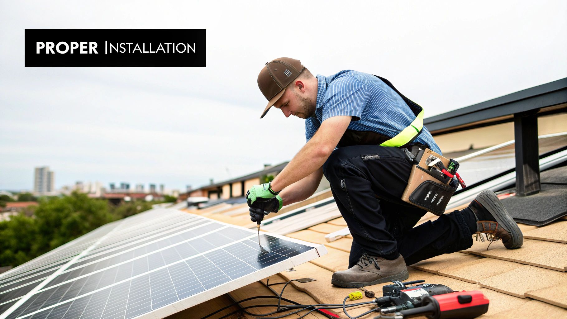
Panels and inverters get the attention. Connectors get the callbacks. After two decades of watching residential rooftops and utility blocks go in, I can tell you the single most common avoidable failure in the field is a bad DC connection — an under-crimped pin, a mismatched mate, a back nut nobody torqued. Industry field data suggests the majority of solar projects encounter at least one connector-related issue over their service life, and a small but real percentage of those escalate to full string shutdowns or fire events.
This guide is the complete field manual for solar cable connectors: how to choose between MC4 and Amphenol H4, what the voltage, current, and IP ratings actually mean on a spec sheet, the NEC rules that will fail your inspection if you ignore them, a step-by-step crimping procedure that eliminates the classic failures, and the troubleshooting workflow our own O&M customers use. Whether you're an installer terminating homeruns, an EPC writing specs, or a developer trying to protect a 25-year revenue model, this is the detail work that decides whether your array outlives its warranty.
⚡ Quick Answer
For most residential and commercial projects, specify genuine UL-listed MC4 connectors (Stäubli or equivalent certified manufacturer) rated for your system voltage (1000V or 1500V DC) and wire gauge, with a minimum IP67 ingress rating. For utility-scale or harsh environments, Amphenol H4 is the rugged alternative. Never mate connectors from different manufacturers — NEC 690.33(C) forbids it. Crimp only with the manufacturer-specified tool and die, perform a pull test on every termination, and torque the back nut with the proper connector wrenches to achieve the rated seal.
A connector is a $2 part that carries every watt your project will ever produce. When one fails, the failure mode isn't graceful: a high-resistance joint heats up under load, the polyamide housing softens and deforms, contact pressure drops further, resistance climbs, and the thermal runaway ends in a melted connector, an open string, or — in the worst cases we've seen in forensic reports — an ignition source on a customer's roof. The physics are unforgiving because DC current never crosses zero; a resistive joint at 600 or 1500 volts has no natural moment to extinguish an arc the way AC circuits do sixty times a second.
The stakes differ by role but they don't shrink:
- For installers: the right connector, correctly terminated, means first-pass inspections and no midnight callbacks. A single connector callback costs more in truck roll than a full pallet of premium connectors.
- For EPCs and developers: connector selection is risk management. A 100 MW block has roughly 400,000 mated pairs in it. At even a 0.1% field failure rate, that's 400 failures over the asset's life — each one lost production plus a service visit.
- For owners: connectors are where "the system is producing 8% low" mysteries usually live. Chasing them costs more than the components ever did.
Field note: we've pulled replacement connectors out of arrays where the installer saved maybe $40 on unbranded "MC4-compatible" parts — and the homeowner paid $400 in diagnostics to find a melted joint on string three. The cheapest connector on the internet is the most expensive one you'll ever buy.
Four connector families cover nearly everything you'll encounter in the field. Two matter for new work; two you'll meet mostly on legacy systems:
| Connector | Common Brands | Voltage Rating | Current Rating | IP Rating | Best Use Case |
|---|---|---|---|---|---|
| MC4 | Stäubli (original), certified equivalents | 1000V / 1500V DC | 30A–50A (gauge dependent) | IP67 / IP68 | Global standard for residential & commercial; maximum ecosystem compatibility |
| Amphenol H4 | Amphenol Industrial | 1000V / 1500V DC | Up to 50A | IP67 / IP68 | Utility-scale and harsh environments; robust latch survives vibration and thermal cycling |
| Tyco SOLKLAMP | TE Connectivity | 1000V DC | ~20A | IP68 | Crimp-free insulation-displacement design; fast field assembly, smaller ecosystem |
| MC3 | Stäubli (legacy) | 600V DC | 20A | IP65 | Obsolete; not compliant for new installs — separable without a tool, failing NEC locking requirements |
The MC4's dominance is earned: it's the connector on the leads of nearly every module shipped today, which means homeruns, whips, and jumpers built on MC4 mate with everything. The H4 earns its spec on big jobs — the locking mechanism tolerates the vibration of tracker rows and the thermal swing of desert sites better, and its contact design holds low resistance through more mating cycles during installation and repowering work.
One more table stakes item on the wire side: the connector is only as good as the conductor it's terminated onto. For rooftop and exposed runs you want PV wire (UL 4703) — thicker, sunlight-resistant insulation rated for direct burial in many cases — while USE-2 remains common for cost-sensitive exposed runs and RHW-2/THHN-2 belongs inside conduit only. Mixing insulation systems mid-string is how ground-fault mysteries start. Our wiring basics guide covers conductor selection in depth, and the NEC compliance guide maps the Article 690 rules behind all of it.
Developed by Stäubli (formerly Multi-Contact), the MC4 is the default interface of the global solar industry. Three things make it the benchmark:
- Locking mechanism. The snap-in latch clicks positively and — per NEC requirements for locking-type connectors — can only be separated with a dedicated disconnect tool. Nobody bumps a mated pair apart under load.
- Installer familiarity. Every certified installer has terminated thousands of them. Familiarity cuts training time and error rates on site.
- Material quality. Genuine MC4s use UV-stabilized polyamide rated for the full 25-year array life, with IP67/IP68 sealing once the gland is properly torqued.
The catch is the clone market. Because "MC4" became a generic term, the market flooded with look-alike parts of unknown alloy, unknown spring temper, and unknown plastic. Some are fine. Many are not. And — critically — even a good clone mated to a genuine Stäubli half is a code violation, which brings us to the rule that fails more inspections than any other.
⚠️ NEC 690.33(C): Never Mate Dissimilar Connectors
The NEC is unambiguous: mated connector pairs must be the same make and model, listed for the purpose. Clicking an "MC4-style" connector from Brand A into one from Brand B — or an MC4 into an H4 — is a code violation, even if they physically fit. Mismatched tolerances create high-resistance contact and seal failures. Inspectors look for this. Warranties die on it. Procure mated pairs from a single trusted source and keep the brands segregated on the truck.
Where the MC4 wins on ubiquity, the Amphenol H4 wins on brute durability. EPCs spec it on utility blocks and punishing climates for three reasons: a locking system built for high-vibration rows, contact materials engineered for extreme thermal cycling and UV load, and the same UL listing and NEC compliance as the MC4. If your project is a fixed-tilt residential roof, MC4 is the pragmatic choice. If it's a 50 MW tracker field in the Sonoran desert, the H4's reputation for being bulletproof is worth the small procurement premium.
Worth saying plainly: neither connector rescues a bad termination. A genuine H4 crimped with the wrong die is still a future hot spot, and a genuine MC4 torqued with channel locks is still a cracked gland waiting for the first storm. The brand decision is the second-order variable. Workmanship, matched mating, and correct tooling are the first-order ones — which is why the procedure section below is the heart of this guide.
A connector spec sheet is the component's vital signs. Four numbers decide whether it's right for your design:
Voltage Rating: 1000V vs. 1500V
Voltage rating — 1000V vs 1500V DC. Residential and small commercial systems live at 1000V and below. Utility and large C&I have moved decisively to 1500V because longer strings mean fewer combiners, less wire, and lower labor. Installing a 1000V-rated connector in a 1500V string is a serious safety and code failure — match the rating to the design maximum, including cold-weather Voc correction per NEC 690.7.
Current Rating (Amps)
Current rating. The connector must carry the circuit's maximum current continuously without overheating — and that rating is wire-gauge dependent. A connector body rated 50A with a contact crimped for 12 AWG is a 30A connector in practice. Match all three: connector, contact, and conductor.
IP rating. The first digit (6 = dust-tight) is standard. The second digit is what you choose: IP67 survives temporary submersion to 1 meter for 30 minutes; IP68 survives continuous submersion per manufacturer spec. IP67 is the floor for any outdoor install. On flat commercial roofs where ponding water is a fact of life, spec IP68 and sleep better.
Temperature range and UV rating. Genuine Tier 1 connectors rate for -40°C to +85°C or better with UV-stabilized housings. Bargain parts rarely publish either number — that silence is your answer.
Matching Connectors to Wire: NEC Ampacity and the 156% Rule
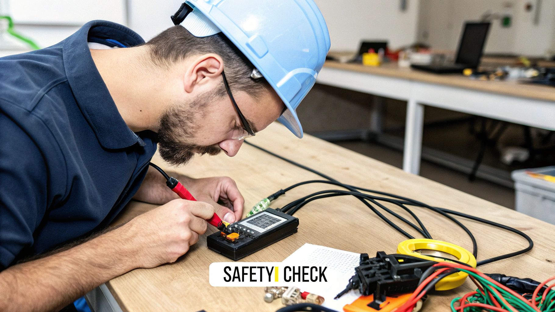
Connector selection and conductor sizing are the same decision. NEC 690.8 requires PV source and output circuit conductors to be sized at 125% of maximum current for continuous operation, times an additional 125% for the irradiance safety factor — 156% of module Isc in most string designs. The connector's contact must be rated for the resulting conductor, and the conductor must be rated for the resulting ampacity after temperature and conduit-fill corrections.
Reference ampacities for the copper PV wire / USE-2 you actually pull, from NEC Table 310.16 (90°C column, before derating):
| Conductor (Cu, 90°C) | Ampacity (NEC 310.16) | Typical Connector Contact Rating | Common Application |
|---|---|---|---|
| 14 AWG | 25A | 20–25A | Short jumpers, low-current legacy strings |
| 12 AWG | 30A | 30A | Residential string homeruns (most common) |
| 10 AWG | 40A | 40A | Longer residential / small commercial runs, voltage-drop control |
| 8 AWG | 55A | 50A | Parallel string outputs, high-current commercial circuits |
Now the sizing math on a real module. Take a modern 450W residential module with Isc = 13.9A:
| Step | Calculation | Result |
|---|---|---|
| Module short-circuit current (Isc) | From module datasheet | 13.9A |
| Continuous duty factor | 13.9A × 1.25 | 17.4A |
| Irradiance enhancement factor | 17.4A × 1.25 | 21.7A required conductor ampacity |
| Conductor selection | 12 AWG PV wire = 30A ≥ 21.7A ✓ | 12 AWG, 30A contact |
| Overcurrent / connector check | Connector rated ≥ circuit maximum | 30A MC4 contact, 12 AWG die |
Two strings paralleled on one output circuit? The math doubles: 2 × 13.9 × 1.56 = 43.3A, which pushes you to 10 AWG minimum before derating, and 8 AWG if rooftop ambient temperatures force a correction factor. I've red-tagged exactly this mistake on plan review — an installer who fused two strings onto a 12 AWG homerun because "the connector fit." The connector always fits. That's not the test.
You can spec the finest connector made and ruin it in eight seconds with the wrong crimper. This is the procedure we teach — follow it and your terminations will outlive the modules:
- Assemble the right tools. The manufacturer-specified crimper with the correct die set for your exact contact and wire gauge, a quality stripper, and the connector wrenches. Pliers and generic crimpers are the number-one cause of failed solar connections. Full stop.
- Cut and strip precisely. Square-cut the PV wire, then strip exactly the insulation length on the manufacturer's datasheet — typically 6–7.5mm. Too short and the crimp grabs insulation; too long and you risk a short at the housing.
- Slide the back nut and gland on first. Before the contact goes anywhere near the wire, thread the back nut and rubber gland onto the cable. Forget this and you're cutting off a perfect crimp. Everyone does it once.
- Crimp until the ratchet releases. Seat the contact in the correct die, insert the stripped conductor fully — every strand inside the barrel — and squeeze until the ratchet clicks and releases. That release is the crimp's certificate of completion.
- Pull test every single termination. A firm tug. If the wire moves at all, cut it off and start over with a fresh contact. An under-crimped joint is a guaranteed hot spot.
- Seat the contact in the housing. Insert until you hear and feel the distinct click. Tug the wire gently to confirm the contact can't back out.
- Torque the back nut with connector wrenches. Compress the gland to a full weatherproof seal — snug and complete, not cracked. Channel locks over-torque and void the IP rating.
- Mate and verify the latch. Click the pair together, confirm the locking tabs are fully engaged, and dress the cable so the mated pair isn't sitting in a puddle path or tensioned against a module frame.
For O&M teams, connector failures are a direct hit to production revenue. Work the diagnosis in this order and you'll find the fault fast. Start with the monitoring data before you ever leave the shop: a string that died abruptly points to an open circuit; a string that faded over weeks points to resistance building at a joint; and a fault that correlates with rain is water ingress until proven otherwise. The truck roll you plan around the data is usually one trip, not three.
| Symptom | Likely Cause | Field Fix |
|---|---|---|
| String producing zero | Open circuit — backed-out contact, broken conductor at a crimp | LOTO, isolate at combiner, continuity-test segment by segment |
| String 5–15% low | High-resistance joint heating under load | Thermal scan under sun; voltage-drop test; replace the hot joint |
| Melted or discolored housing | Under-crimp or mismatched mate reached thermal runaway | Replace pair; inspect adjacent connectors; test full string |
| Ground-fault trips after rain | Water ingress from loose gland or cracked housing | Find the wet joint (insulation resistance test); reseal or replace |
| Connector won't separate | Wrong disconnect tool or damaged latch | Use the correct unlock tool; never pry — replace if latch is damaged |
Two rules from hard experience. First, a burnt connector is a symptom, not the disease — inspect the neighbors and megger the string before you button it back up, because the fault that cooked one joint often cooked several. Second, thermal imaging on a sunny day is the single highest-value diagnostic in the O&M kit: a resistive joint lights up like a road flare while the good connections around it stay dark. We spec a scan on every commissioning checklist now, and it catches the one-in-a-hundred bad crimp before the customer ever sees a low string on their monitoring app.
Three procurement rules that have never failed us:
- Buy mated pairs from one manufacturer per project. Segregate brands by project in the warehouse and on the truck. Mixed inventory is how 690.33(C) violations happen.
- Demand the listing, not the claim. "MC4 compatible" is marketing. UL 6703 listing for the specific mated pair is compliance. Ask for the file number.
- Buy the tools with the connectors. The crimper, dies, and wrenches for your chosen contact system, on the same PO, so no tech is ever tempted to improvise with what's on the truck. Improvised tooling is where warranty claims go to die.
At PES Supply we stock listed connector systems, PV wire by the spool, and the manufacturer-matched tooling — see our electrical supplies category, or get a bulk quote for project-scale volumes. If you're speccing the rest of the DC side, our solar panel wiring guide and NEC compliance guide pair well with this one.
Nobody worries about one connector. The risk lives in the count. Run the numbers on a 1 MW commercial block using modern 550W modules and you start to see why connector discipline is an operations problem, not a hardware preference:
| Design Parameter | Math | Result |
|---|---|---|
| Modules per 1 MW block | 1,000,000 W ÷ 550 W | ~1,818 modules |
| Mated pairs per module (leads) | 2 per module | ~3,636 pairs at module-to-module links |
| Field-terminated pairs (homeruns, jumpers, whips) | ~2–4 per string × ~110 strings | ~220–440 field terminations |
| Total mated DC connections per MW | Factory + field | ~3,900–4,100 per MW |
Four thousand connections per megawatt. A 100 MW utility site is pushing 400,000 mated pairs. Now apply field-reported failure distributions: if even one termination in a thousand is defective, that's 400 defects on a 100 MW site — each one a hot spot, a lost string, or a warranty argument. This is why the big EPCs run connector QA as a formal work package: calibrated crimpers with maintenance logs, pull-test sampling per crew per day, torque audits on gland nuts, and thermal scans at commissioning. The $2 part gets a QA program because the math forces it.
The industry's shift from 1000V to 1500V system voltage changed connector procurement on large sites. Longer strings — often 28 to 35 modules per string at 1500V versus 18 to 22 at 1000V — cut the string count, the homerun footage, and the combiner count on a project by roughly a third. Fewer connections is less failure surface, and that alone justified the transition for most developers.
But 1500V raises the stakes on every remaining connection. The arc energy available at 1500V DC is punishing, DC arcs don't self-extinguish at zero-crossing the way AC arcs do, and a marginal connection that might have simmered at 600V becomes an ignition risk at 1500V. The procurement rules tighten accordingly: every connector in the chain — module leads, jumpers, homeruns — must carry a 1500V rating as a matched, listed system, and the mixed-mating prohibition in NEC 690.33(C) goes from "important" to "the thing your insurer will ask about after a fire." Cold-climate designers also have to check the other direction: NEC 690.7's temperature correction can push string open-circuit voltage up 20% or more on the coldest design morning, and that corrected Voc is what your connector voltage rating has to clear.
After watching hundreds of crews terminate everything from single rooftops to 50-acre blocks, the pattern among the good ones is boring and consistent:
- One connector system per project, staged by kit. Housings, contacts, glands, and tools ship together per crew, per day. No communal bins where Brand A and Brand B contacts mingle.
- Calibrated crimpers with a log. Crimp tools drift. A calibration check at shift start, recorded, is a two-minute habit that has ended more warranty disputes in the contractor's favor than any lawyer.
- Documented pull tests. A sample rate per crew per day — commonly one in fifty on utility work — logged by string number. When an insurer asks how you know the terminations were sound, the log is the answer.
- Commissioning thermal scan. A full-array infrared pass under load before handover. The scan catches the statistical bad crimp while the crew is still mobilized, when fixing it costs a ladder climb instead of a truck roll.
We supply into programs like this every week, and the contractors who run them almost never call us about connector failures. The ones who buy connectors as an afterthought — whatever's cheapest that fits — are the ones calling about thermal events two summers later. Correlation isn't perfect, but it's loud.
Can you mix and match different brands of MC4 connectors?
No. NEC 690.33(C) requires mated pairs to be the same make and model, listed for the purpose — even if two "MC4-style" connectors physically click together. Mismatched tolerances create high-resistance contact and failed seals, leading to heat, moisture ingress, arc faults, failed inspections, and voided warranties. Always procure mated pairs from a single manufacturer per project.
What is the difference between MC4 and Amphenol H4 connectors?
Both are UL-listed, 1000V/1500V-rated, IP67/IP68-sealed locking connectors. The MC4 is the global standard found on nearly every module lead, maximizing compatibility. The Amphenol H4 offers a more robust latch and contact system favored for utility-scale arrays, high-vibration tracker rows, and extreme climates. Choose MC4 for residential/commercial ecosystem compatibility; H4 where durability under punishment is the priority.
How long do solar connectors last?
A genuine Tier 1 connector, correctly crimped and sealed, is designed to last the full 25–30 year life of the array. Longevity depends on workmanship (correct die, full ratchet cycle, proper gland torque) and material quality (UV-stabilized polyamide). Uncertified knock-offs often become brittle and crack within a few years of sun exposure, which is why they fail early.
What wire gauge should I use with MC4 connectors?
Match the contact to the conductor and the conductor to NEC sizing. Most residential strings run 12 AWG PV wire (30A at 90°C per NEC 310.16), which covers a module Isc up to about 19A after the 156% factor. Paralleled strings or high-ambient rooftops may require 10 or 8 AWG — and a contact crimped for 12 AWG turns a 50A connector body into a 30A component, so size all three together.
How tight should a solar connector back nut be?
IP Rating (Ingress Protection)
How Tight Is "Tight Enough" for a Connector?
Tight enough to fully compress the internal rubber gland against the cable jacket — "wrench snug" using the manufacturer's plastic connector wrenches. Under-tightening breaks the IP67/IP68 seal and invites moisture; over-tightening with channel locks cracks the housing and strips threads, voiding the ingress rating. For the mated connection itself, the audible click of the latch is the confirmation.
Are MC3 connectors still code-compliant?
No — not for new installations. The legacy MC3 is rated only 600V and 20A, carries an IP65 seal, and can be separated without a tool, failing the NEC's locking-connector requirements for PV circuits. You'll still find MC3s on older arrays; treat them as replace-on-touch during service and repowering work.
Connectors, PV Wire & Matched Tooling — In Stock
Listed connector systems, spooled PV wire, and manufacturer-matched crimp tooling with nationwide LTL freight from Louisville, KY. Bulk pricing for project volumes.
Shop Electrical Supplies Get a Bulk QuoteRelated Guides & Resources
- Solar Panel Wiring Basics — DC conductor sizing done right
- Solar Installation Guide — design to commissioning
- NEC Code Compliance Guide
- Grounding & Bonding Guide
- Solar Installation Guide (Homeowner)
- Solar Maintenance Guide
- Solar Panel Mounting Guide
- Solar Panels
- Solar Inverters
About PES Supply
Your Top Questions About Solar Connectors, Answered
PES Supply is a nationwide distributor of Tier 1 solar panels, inverters, battery storage, racking, connectors, PV wire, and complete electrical project kits — 50,000+ SKUs across 169 authorized brands with full OEM warranties and nationwide LTL freight from our Louisville, Kentucky supply house. Phone: 1-888-876-0007 • portlandiaelectric.supply