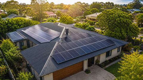
K2 Systems did not invent solar mounting, but the German-engineered racking house has arguably done more than anyone to professionalize it over the past two decades. From standing-seam clamps that hold through hurricane seasons to ballasted flat-roof systems that go down with minimal penetrations, K2's hardware shows up on residential, commercial, and utility roofs across more than a hundred countries. This guide covers how modern mounting technology evolved, where K2's system families fit, the structural engineering that separates a code-compliant array from a future insurance claim, and the field practices that make racking the single most reliable part of a solar project instead of its weakest link.

The Evolution of Solar Mounting Systems
The history of solar cannot be told without the mounting systems underneath it. Early arrays rode on site-fabricated brackets and repurposed strut channel — heavy, slow to install, and allergic to the roof types they met. The industry's first professional generation brought aluminum rail systems with engineered attachments. The current generation, where K2 Systems has been a consistent innovator, treats the racking as a designed structural system: tested load paths, pre-engineered span tables, integrated grounding, and digital design tools that output stamped-ready documentation.
The drivers behind that evolution are unglamorous and decisive. Labor is the largest controllable cost on most installs, so every click-connection and pre-assembled component that removes minutes per module shows up directly in margin. Code enforcement has tightened steadily, so engineered load documentation moved from nice-to-have to permit-required. And module formats keep changing — bigger, heavier, bifacial — so racking has to adapt without a ground-up redesign every two years.
Where K2 Systems Fits in the Industry
K2 Systems built its reputation on precision-engineered, highly adaptable mounting hardware with a design philosophy installers recognize immediately: fewer unique parts, more shared components, and connections that assemble one obvious way. The company's K2 Base design software generates project-specific structural calculations and bill-of-material outputs, which matters more than any single product — it converts racking from a purchasing decision into an engineered deliverable.
In the North American channel, K2 competes alongside IronRidge, Unirac, and SnapNrack — all credible systems we stock and sell. The honest differences come down to installer preference, span economics on the specific roof, and which design tool your office has standardized on. We carry K2 Systems because a meaningful share of our contractor customers standardized on it, and because its flat-roof and metal-roof solutions solve real problems elegantly.
The K2 System Families and What Each One Solves
| System Family | Roof/Application Type | Design Character |
|---|---|---|
| CrossRail / SingleRail (pitched roof rail systems) | Composition shingle, tile, metal roofs | Shared-rail architecture, wide module compatibility, engineered spans |
| S-Dome / D-Dome (flat-roof ballasted) | Low-slope commercial membrane roofs | Low ballast requirements, minimal or no penetrations, aerodynamic wind deflection |
| MiniRail / short-rail systems | Metal roofs, trapezoidal and corrugated profiles | Compact footprint, fast install on profile ribs |
| Standing seam clamps | Standing-seam metal roofs | Non-penetrating attachment to seam ribs |
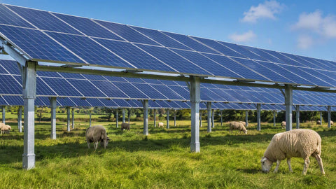
| Ground-mount solutions | Open land, agricultural, small utility | Pile-driven or ballasted foundations, high-wind engineering |
Product details evolve; confirm current specifications and compatibility with K2's documentation or our team before finalizing a BOM.
The pattern across the families is the K2 signature: the same connection logic and many of the same components carry across roof types, so a crew trained on pitched-roof CrossRail is already most of the way trained on flat-roof Dome systems. For installers running mixed residential-commercial books, that training economy is worth real money.
The Structural Engineering That Actually Matters
Racking is a structural system holding a large, flat sail to a building for 25-plus years. The governing standard in the U.S. is ASCE 7 for wind and snow loads, and every legitimate racking system publishes test data and span tables keyed to it. Here is the shape of the math, with a worked example:
| Load Design Step | Reference | Worked Example (120 mph, Exposure C) |
|---|---|---|
| Basic wind speed & exposure | ASCE 7 Ch. 26–27 | 120 mph ultimate, open terrain |
| Velocity pressure qz | qz = 0.00256 × Kz × Kzt × Ke × V² | ≈0.00256 × 0.9 × 1.0 × 1.0 × 120² ≈ 33.2 psf |
| Net pressure with coefficients | ASCE 7 rooftop solar provisions | ≈33.2 × GCrn (say 1.2 edge zone) ≈ 40 psf uplift, edge |
| Tributary area per attachment | Racking span table | 6 ft span × 5.5 ft rail spacing ≈ 33 sq ft |
| Uplift per attachment | Pressure × area | ≈40 × 33 ≈ 1,320 lbs — check attachment rating |
That final number is why attachment spacing is not a suggestion. A lag or clamp rated for the load at 6-foot spacing may be hopelessly undersized at 8-foot spacing, and the difference between interior-zone and edge-zone pressures routinely doubles the requirement at the roof perimeter. Every year I hear about an array that "passed inspection" but peeled in its first real storm because someone averaged the zones. Use the racking manufacturer's engineering letters, honor the zone map, and when the site is genuinely odd — parapet turbulence, rooftop equipment, unusual geometry — pay for the project-specific engineering. It is the cheapest insurance in the entire build.
Span Economics: Where Racking Cost Is Actually Won
Racking cost per watt is driven less by rail price than by attachment count, because attachments carry the labor: find the rafter, seal the penetration, torque the fastener. A rail system with stiffer profiles and longer allowable spans needs fewer attachments per module row. The arithmetic on a 24-module residential array illustrates it:
| Attachment Spacing | Attachments per Row (typ.) | Total Attachments (4 rows) | Relative Labor |
|---|---|---|---|
| 4 ft | 12 | 48 | Baseline +50% |
| 6 ft | 8 | 32 | Baseline |
| 8 ft (where spans allow) | 6 | 24 | Baseline −25% |
Sixteen fewer attachments on a single residential job is an hour-plus of crew time, sixteen fewer roof penetrations, and sixteen fewer leak risks over the array's life. Multiply across a hundred jobs a year and span capability stops being a spec-sheet detail and becomes a business model. This is the lens I use when contractors ask why one rail line costs more per foot than another — the expensive rail that spans farther is often the cheaper system installed.
Flat-Roof Ballasted Systems: The Dome Approach
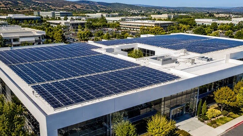
Low-slope commercial roofs are where K2's Dome-family design philosophy shines: aerodynamic deflectors that let wind flow over the array instead of under it, south-facing or dual-tilt configurations, and ballast requirements engineered to the roof's zones. The ballast math is the part owners ask about, so here is a representative framing — always use the system-specific engineering output for real designs:
| Design Factor | Interior Zone | Edge/Corner Zone |
|---|---|---|
| Relative ballast requirement | Baseline | 1.5–2.5× baseline (typical pattern) |
| Roof structural check | Dead load + ballast vs. roof capacity | Same, at worst-case zone |
| Membrane protection | Slip sheets / pads under ballast trays | Same, plus deflector attachment checks |
| Penetrations | Often zero | Sometimes required by engineering — plan roof warranty coordination |
Two field rules on ballasted work. First, never skip the roof membrane conversation: ballast trays on bare membrane without protection pads is a leak claim waiting for its fifth anniversary. Second, confirm the roof's remaining structural capacity with the ballast, not just the panels — I have seen a project value-engineered into trouble when a light racking system was swapped without re-checking that its ballast requirement was heavier.
Installation Practices That Separate Clean Jobs From Callbacks
- Torque everything to spec. Racking manufacturers publish torque values for every connection; "impact driver tight" is not a torque value. Calibrated tools, spot-checked.
- Respect thermal expansion. Long rail runs expand and contract; splices belong where the engineering puts them, and rails should never be hard-butted against obstructions.
- Flash every penetration. A lag without flashing is a slow leak with a warranty denial attached. Use the flashed attachment systems the roof type calls for.
- Bond the path, then verify it. Integrated bonding clamps are excellent — when installed per instructions. Spot-check continuity rail-to-rail and rail-to-module per the grounding and bonding guide.
- Document as-built attachment spacing. Photograph the layout before modules go on. The next storm claim will be easier.
I will put my name on this opinion after years of storm-season phone calls: most "racking failures" are not racking failures. They are engineering failures — spans stretched past table values, zones ignored, attachments improvised — wearing a racking label. The hardware from K2, IronRidge, Unirac, or SnapNrack all performs when installed inside its engineering envelope. Buy the system your crew knows, follow its tables without creativity, and racking becomes the least interesting part of your project — which is exactly, precisely what you want after the last module is set.
Mounting's Role in the Energy Transition

Zooming out, mounting technology is quietly one of the enabling layers of the clean-energy buildout. Faster-installing systems cut the soft-cost drag that keeps solar expensive. Non-penetrating flat-roof systems open the enormous inventory of commercial membrane roofs that owners refused to pierce. Better wind engineering opens coastal and plains markets that conservative jurisdictions once froze out. When people ask me where solar's next cost reductions come from, they expect me to say modules or batteries. Half the time, the honest answer is steel, aluminum, and the engineering software that tells you where to put them.
Browse our solar mounting systems, roof mount kits, mounting parts, and racking hardware kits for current stock, see the racking systems overview for cross-brand comparison, and use the system calculator to size the array your racking will carry. For ground-mount projects, our 24-panel ground-mount kit shows what a pre-engineered package looks like. Questions on spans, loads, or system selection — contact our team.
Early Industry Challenges — and How Modern Racking Fixed Them
Ask anyone who installed solar before 2010 and the racking stories come out fast. Rails were cut on site with whatever saw was in the truck. Attachments were generic L-feet bolted through shingles with a prayer for flashing. Every roof type meant a different hardware bag, and "engineering" was a span table photocopied so many times the numbers blurred. Installs were slow, leaks were common, and inspectors treated every array as a novel structure because, structurally speaking, it was.
Three shifts fixed it. First, systems thinking: manufacturers like K2 began shipping complete, tested assemblies — rail, splice, clamp, attachment, flashing — engineered as one load path instead of a hardware store of parts. Second, software: design tools like K2 Base turned site inputs into stamped-ready calculations, converting permitting from an argument into a submission. Third, standardization of training: when a crew installs the same connection logic on every roof, quality stops depending on who showed up that morning. The racking on a professional install today is unrecognizable from that era, and the industry's leak-and-failure statistics show it.
Standing-Seam Metal Roofs: The Non-Penetrating Ideal
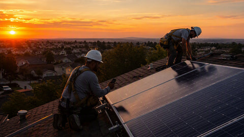
Standing-seam metal is the best solar roof nobody plans for. The raised seams are purpose-built attachment points: seam clamps grip the rib with set screws, transfer load directly into the panel and purlin structure, and never pierce the weather surface. Zero penetrations means zero leak risk from the array — on a roof that often outlasts the building's interior finishes, that pairing is nearly permanent infrastructure.
K2's seam-clamp solutions and its competitors' equivalents all exploit this, but the details matter: clamp models match specific seam profiles and gauges, and set-screw torque is specified, tested, and absolutely not optional. I have inspected a metal-roof array where a crew used clamps rated for a snap-lock seam on a mechanically seamed profile — it held for two years, then a wind event walked three modules off the south row. Match the clamp to the seam, torque to spec, and a standing-seam install is the fastest, cleanest racking job in the business.
Ground-Mounts: Where Racking Becomes Civil Engineering
Ground-mounts strip away the roof and leave the racking to face wind, snow, frost heave, and soil on its own. Foundation choice — driven piles, ground screws, or concrete ballast — depends on soil class, frost depth, and whether anyone plans to farm or mow around the array for the next three decades. Pile-driven systems dominate for cost and speed where soils cooperate; ballasted blocks serve rocky or environmentally sensitive sites; ground screws split the difference.
The engineering stakes scale with the sail area. A 24-module ground array presents roughly 550 square feet of wind surface; at a 40 psf design pressure that is over 20,000 pounds of force looking for a weak weld or a shallow pile. This is why pre-engineered packages with stamped foundations — like the 24-panel Sky Rack ground-mount kit we stock — have taken share from site-fabricated structures: the engineering is done, tested, and insurable before the truck arrives.
Corrosion, Compatibility, and the 25-Year Materials Question
An array's racking must survive the same 25–30 years as the modules above it, outdoors, in every thermal cycle and storm. Aluminum rail and stainless or coated fasteners are the industry answer, with one persistent trap: galvanic corrosion at dissimilar-metal interfaces. Aluminum rail on steel structure, stainless fasteners in aluminum extrusions, copper grounding against aluminum frames — each pairing is manageable with correct isolation and listed hardware, and each becomes a corrosion cell when someone improvises with whatever was in the van. Coastal salt environments accelerate everything; in salt-air markets, specify the corrosion-tested component lines and double the inspection cadence.
The NEC side of materials compatibility — bonding and grounding path integrity — is covered in our grounding and bonding guide, and it intersects with racking constantly: integrated bonding clamps only work when the module frame and rail coatings match the clamp's listed compatibility. Read the listing. The inspector will.
Permitting and Documentation: The Paperwork Advantage
Here is a competitive reality that rarely gets said out loud: on commercial work, the racking system's documentation package can matter as much as its hardware. AHJs increasingly expect project-specific structural letters, and utilities and lenders expect as-builts that match them. Systems backed by strong design software generate these artifacts as a byproduct of the layout process — spans, loads, attachment schedules, ballast maps — while value-engineered racking often leaves the EOR scrambling. When we quote racking for commercial customers, we quote the documentation with it, because a racking system that delays permitting by three weeks is not the cheap option no matter what the rail costs per foot.
Choosing a Racking Partner: The Short List of Questions
- Does the system have tested, published span and load data for my roof type, my design wind speed, and my snow load?
- Does the design tool produce documentation my AHJ accepts without revision cycles?
- Are components shared across the roof types my crews actually encounter week to week?
- What is the realistic installed labor per module — not the brochure time, the real crew time?
- Can I get replacement parts and odd-attachment inventory from my distributor without a six-week wait?
That last question is where we come in. Racking emergencies do not schedule themselves: a shorted pallet of mid-clamps or a surprise tile roof can idle a crew at $400 an hour. Our Louisville warehouse stocks deep across K2, IronRidge, Unirac, and SnapNrack lines plus the loose parts that save jobs, with nationwide freight that understands what "crew on the roof tomorrow" means. When a job needs a weird tile hook, a longer rail, or a ballast tray variant nobody planned for, that inventory depth is the difference between a same-week fix and a slipped schedule.
The Future: Where Mounting Technology Goes Next
Three trends are shaping the next racking generation, and all three are already visible in current product lines. First, module-format agility: as modules grow past 2.3 meters and 30 kg, racking is adapting with wider clamping ranges and higher load envelopes rather than forcing redesigns every product cycle. Second, electrification integration: racking increasingly carries wire management, rapid-shutdown devices, and module-level electronics as designed features instead of field add-ons — the rail is becoming the array's nervous system carrier. Third, software-first engineering: the layout-to-stamped-documents pipeline keeps compressing, and the winners in commercial racking will be the systems whose software output an AHJ approves without a phone call.
K2's trajectory — component sharing across roof types, aerodynamic flat-roof design, and the K2 Base platform — tracks all three trends, which is why it remains a default recommendation in our commercial conversations. But the broader point stands regardless of brand: mounting has graduated from commodity hardware to engineered infrastructure, and projects that treat it that way finish faster, permit easier, and survive their storm seasons.
A Note on Training and Crew Economics
One factor that never appears on a spec sheet but decides real-world racking outcomes: crew familiarity. A system your installers know deeply installs faster, torques correctly, and survives inspection; an unfamiliar system — however elegant — gets installed slowly and sometimes wrong. This is why we rarely push customers to switch racking brands over marginal hardware differences. The better move is usually to master one system family per roof type, stock its parts deeply, and let repetition do the quality work. If you are building that standard now, K2's cross-roof component sharing makes it one of the easier families to standardize on.
Frequently Asked Questions
- What is K2 Systems known for?
- German-engineered pitched-roof, flat-roof, metal-roof, and ground-mount racking, plus the K2 Base design software that outputs project-specific structural calculations.
- How is wind load calculated for solar racking?
- Per ASCE 7: velocity pressure times zone-specific net pressure coefficients times tributary area per attachment. Edge zones can double the load.
- Why does rail span matter?
- Attachments drive labor and leak risk. Longer allowable spans cut attachment count by up to 25% per job.
- Do ballasted flat-roof systems penetrate the roof?
- Often no — aerodynamic ballast holds many configurations — but high-wind edge zones sometimes require penetrations per engineering.
- How does K2 compare to IronRidge, Unirac, SnapNrack?
- All are credible tested systems; the differences are crew familiarity, span economics, and design-software standardization. We stock all four.
- What causes most racking failures?
- Engineering and installation errors — overspanned rails, ignored zones, unflashed penetrations — not the hardware itself.