Your Blueprint for Solar and Battery Integration
Connecting solar panels to a battery bank is the core skill of off-grid and hybrid power — get the architecture right and the system quietly runs for decades; get it wrong and you're replacing batteries on a schedule that will make you hate the sun. This guide covers the professional workflow: component selection, wiring topology, the connection sequence, charge programming, and the safety checklist that separates an installation from an experiment. Every number in it is one we use on real jobs, and every warning in it was learned the expensive way so you don't have to.
The scale here is bigger than the single-panel shed build — we're talking arrays of two to twenty panels feeding banks measured in kilowatt-hours, the territory of cabins, off-grid homes, and serious RVs. (For the one-panel version of this project, start with connecting a single solar panel to a battery.) The principles are identical; the consequences of sloppiness scale with the wattage.
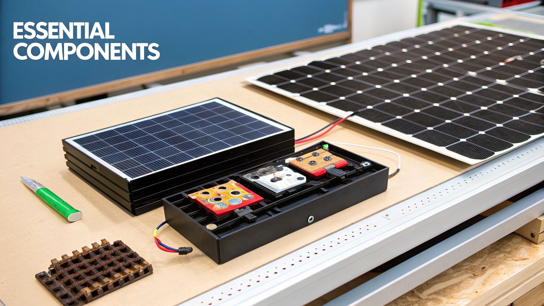
Core Components for a Solar Panel to Battery Connection
| Component | Primary Function | Critical Role in System |
|---|---|---|
| Solar Panels | Convert sunlight into DC electricity | The energy source for the entire system |
| Solar Charge Controller | Regulates voltage and current from panels | Protects the battery from overcharging, maximizing its operational lifespan and safety |
| Battery Bank | Stores DC energy for later use | Provides power when solar generation is unavailable, ensuring energy resilience |
| Inverter | Converts DC power from the battery to usable AC power | Makes stored solar energy compatible with standard building loads and appliances |
| Wiring & Fusing | Safely transmits power between components | Ensures NEC-compliant operation and protects the system from overcurrent faults |
Choosing the Right Hardware for Your Project
Sizing Your Core Components
Size in this order, always: loads first, battery second, array third, controller fourth, inverter fifth. Loads decide how much energy the bank must hold; the bank decides how much array must refill it daily; the array decides the controller; the peak load decides the inverter. Working backwards from a panel somebody already bought is how mismatched systems get born.
The quick math chain for a cabin using 4 kWh per day at 4.5 peak sun hours: battery ≥ 4 kWh × days of autonomy ÷ usable DoD (two days lithium: 4 × 2 ÷ 0.9 ≈ 8.9 kWh — call it two 5.4 kWh rack modules); array = 4 kWh ÷ 4.5 ÷ 0.75 ≈ 1.2 kW minimum, spec 1.6–2 kW for weather margin (four or five 400W panels); controller = array watts ÷ bank volts × 1.25 (1,600 ÷ 24 × 1.25 = 83A → a 100A MPPT or split across two controllers). The battery sizing calculator and our off-grid storage sizing guide run this chain for bigger houses.
Selecting the Right Technology
Controller technology: MPPT, full stop, at this scale. PWM's voltage-clipping waste is tolerable on a 100W shed panel and inexcusable on a 2 kW array — the 20–30% harvest difference pays the price gap in the first year, and everything after that is free watts. Battery chemistry: LiFePO4 owns new builds unless extreme cold without battery heating forces AGM; the 90%+ usable DoD and 3,000+ cycle life beat lead-acid's 50% DoD and 500 cycles on every multi-year spreadsheet we've ever run — the lead bank costs less on invoice day and more every year after. Rack-mount 48V modules have become the default architecture past 5 kWh — the LiFePO4 collection shows why: communications-enabled BMS, stackable capacity, and no cable-balancing gymnastics.
Controller shopping maps directly to array size: compact MPPTs like the Victron SmartSolar 100/50 cover single-string kilowatt-scale builds; the 150/100 or MidNite's line (the MN3024DIY for 24/48V banks) covers multi-string arrays. Our controller sizing guide has the full selection tree.
The Hands-On Wiring and Connection Process
Step 1: Connect Battery to Charge Controller
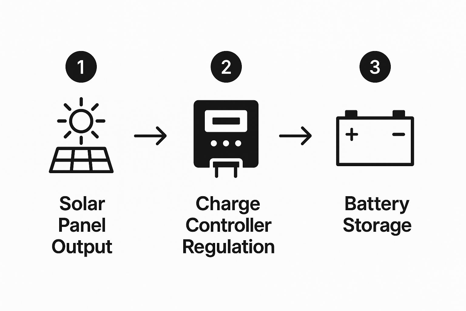
Battery first, panels last — the controller boots from battery voltage and configures itself around what it sees. Fuse the positive conductor within inches of the bank, sized to the wire and controller rating. On 48V rack banks, follow the manufacturer's interconnect order exactly; the modules negotiate addresses on first boot, and improvising the sequence earns you a troubleshooting afternoon. I've watched a crew spend four hours chasing a "bad module" that was just a bank commissioned out of order — power down, follow the manual, problem gone.
Step 2: Connect the Solar Array to the Charge Controller
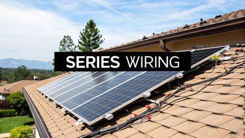
Array wiring arrives at the controller through a combiner (multiple strings) or directly (single string), with a PV-rated disconnect in between — the MidNite MNEPV breaker family is the standard answer for DC-rated overcurrent and disconnect duty. Verify string open-circuit voltage against the controller's absolute max input with the cold-weather correction before landing anything: a string that's 380V in July is 430V in January, and "absolute maximum" on a controller datasheet is not a guideline. Full cold-voltage math lives in our series wiring guide.
Step 3: Wiring for Voltage and Capacity
| Wiring Configuration | Impact on Voltage | Impact on Amperage/Capacity | Best Use Case |
|---|---|---|---|
| Series | Voltage adds up (V1 + V2...) | Amperage stays the same | Increasing PV array voltage for an MPPT controller to improve efficiency and reduce wire size over long runs |
| Parallel | Voltage stays the same | Amperage/Capacity adds up (A1 + A2...) | Increasing total amp-hour capacity of a battery bank or total current of a PV array without changing nominal system voltage |
The professional pattern at cabin scale and above: series the panels into strings (high voltage, small wire, low loss), parallel the strings at the combiner only as needed, and parallel battery modules at a common busbar with equal-length cables. Series batteries only when stepping system voltage, and only with matched units. Every parallel battery leg gets its own fuse; every parallel string beyond the second gets string fusing per NEC 690.9. The MC4 wire gauge guide and solar cable guide cover conductor and connector selection for the array side.
Array-to-Controller Matching: The Two Numbers That Must Fit
Every controller has two hard ceilings, and the array must fit under both simultaneously:
| Controller Limit | What It Protects | How to Check | Example (100/50 MPPT, 24V bank) |
|---|---|---|---|
| Max PV input voltage (Voc) | Input electronics — instantaneous damage if exceeded | String Voc × cold-weather correction factor ≤ controller max | 100V ceiling ÷ corrected 44V per panel → 2 panels per string max |
| Max charge current (A) | Output stage — over-paneling wastes harvest, not hardware | Array watts ÷ bank volts ≈ charge amps; oversizing ~20% is accepted practice | 50A × 24V = 1,200W nominal array; 1,400W array works, clips at solar noon |
Voltage is the killer, current is the budget. Exceed the voltage ceiling once — one cold, bright morning — and the controller is dead before coffee. Modest over-paneling on current, by contrast, is a deliberate pro move: the array clips a few percent at perfect-noon and harvests meaningfully more every other hour of the year. The hybrid inverter guide covers the integrated alternative where controller and inverter share one chassis.
System Commissioning and Safety Protocols
Programming Critical Charge Parameters
Charge parameters come from the battery manufacturer, never from the controller's defaults. Defaults assume generic lead-acid; a lithium bank charged on lead-acid defaults undercharges daily and gets equalization-cooked if the setting is enabled:
| Parameter | Flooded Lead-Acid | AGM | LiFePO4 (typical spec) |
|---|---|---|---|
| Absorption voltage (12V bank) | 14.4–14.8V | 14.2–14.6V | 14.2–14.6V |
| Absorption time | 2–4 hrs | 2–4 hrs | 0–30 min (voltage-based tail) |
| Float voltage | 13.4–13.8V | 13.4–13.8V | 13.6V or disabled |
| Equalization | 15.5V+, monthly-ish | Only if manufacturer allows | Never — disable permanently |
| Low-temp charge cutoff | Not required | Not required | 32°F — BMS or controller must enforce |
Scale the 12V numbers ×2 for 24V banks and ×4 for 48V. After programming, verify: watch one full charge cycle and confirm the controller actually reaches absorption voltage and transitions — a system that never finishes charging is usually an undersized array or a wrong setting telling on itself.
Essential Safety Checklist Before System Activation
| Check Point | Verification Method | Importance |
|---|---|---|
| Correct Polarity | Multimeter confirmation of positive (+) and negative (−) at all DC connection points | Critical |
| Torque Specifications | Calibrated torque wrench on all terminal lugs against manufacturer specs | Critical |
| Overcurrent Protection | Correctly sized and rated fuses/breakers installed on all required circuits | Critical |
| System Grounding | Visual inspection plus multimeter continuity test of the equipment grounding system | Critical |
| Wire Management | All wires secured, protected from physical damage, no exposed conductors | High |
| Disconnects Labeled | All AC and DC disconnects clearly, legibly, permanently labeled per NEC | High |
Run the checklist physically, with a second person reading and the builder touching each item. The version in your head misses the one loose lug that the version on paper catches — and on a 48V bank, a loose lug under load is an arc-flash event, not a spark. Grounding specifics for permitted systems live in the grounding and bonding guide, and overcurrent/disconnect requirements in the NEC 690 disconnect guide.
Boosting Performance for Longevity and ROI

Commissioned and safe is the floor, not the ceiling. The difference between a system that meets spec and one that beats it is operational: load timing, log reading, and small habits that compound into years of extra battery life.
Maximizing Self-Consumption and System Value
Off-grid, self-consumption is the whole game — every watt-hour used at noon is a watt-hour the battery never has to store. Shift discretionary loads (laundry, water pumping, tool charging, ice making) into solar hours and the effective battery size grows without buying anything. Hybrid systems with grid access flip the logic: the battery shifts solar into evening rates, and the battery runtime calculator quantifies how long the bank carries the house when the grid drops.
Interpreting System Data for Proactive Maintenance
Modern MPPT controllers and battery BMS units log everything — harvest kWh, peak volts, min/max battery voltage, charge stage hours. Read the logs monthly. The signatures that matter: daily harvest trending down with clean panels suggests shading growth or a failing string; charge time stretching suggests battery capacity fade; a bank that never reaches absorption is chronically undercharged and aging fast. Fifteen minutes of log review per month has caught more dying systems early than any other habit we teach, including the customer whose "fine" cabin system had been bulk-charging for six hours a day — the array was feeding a bank that could no longer accept the amps. New modules under warranty beat new modules at retail.
Choosing Your System Voltage: 12V, 24V, or 48V
System voltage is the first architecture decision and the one everything else inherits. The physics: power is constant, so higher voltage means lower current — and current is what sizes wire, fuses, and controller dollars.
| System Voltage | Sweet Spot | Array Ceiling (practical) | Inverter Ceiling (practical) | Failure Mode Past the Limit |
|---|---|---|---|---|
| 12V | RVs, boats, single-battery builds | ~400W | ~1,000W | Controller costs and wire sizes explode; voltage drop eats harvest |
| 24V | Cabins, vans, 2–5 kWh banks | ~1,500W | ~3,000W | Multiple controllers needed; 2/0 cable territory on big inverters |
| 48V | Off-grid homes, 5+ kWh banks | 5,000W+ per controller | 8,000W+ hybrid inverters | None practical at residential scale — the modern default for serious builds |
The 48V rack ecosystem is why we steer cabin-scale builds past the 24V decision quickly: one 100A controller swallows a 5 kW array, a Sol-Ark 8K-class hybrid inverter runs the whole house side, and rack modules stack capacity without cable-balancing craft. We still sell plenty of 12V gear — the RV world runs on it — but a fixed building with a 5 kWh bank is a 48V system waiting to be admitted.
Combiners, Disconnects, and the DC Balance of System
Between the array and the controller lives the balance of system that inspectors actually inspect. The stack, in order from array to controller: string wiring → string fuses (when 3+ strings parallel, per NEC 690.9) → combiner box → main PV disconnect → controller input. Each string fuse sizes at 1.56 × Isc rounded to the next standard rating; the main disconnect rates at 1.25 × combined short-circuit current, again rounded up. Every enclosure outdoors is NEMA 3R minimum, and every disconnect gets a permanent label stating what it isolates.
Two details that pass inspections and prevent callbacks: torque every combiner lug to spec at install and again at the one-year check (thermal cycling walks lugs loose), and leave a printed string map inside the combiner door. The technician who services this system in 2031 — possibly you — will thank whoever did that. We stock the combiners, PV breakers, and enclosures at the counter precisely because this layer is where hand-built systems most often cut corners.
Seasonal Operations: Winterization and the Cold-Charging Hard Stop
Battery chemistry meets weather at 32°F. LiFePO4 cannot accept charge below freezing without cell damage — plated lithium, dead modules, voided warranties. The defenses, in order of robustness: install the bank indoors or in an insulated enclosure; use heated rack modules that warm themselves before accepting charge; or configure the charge controller's low-temperature cutoff when the BMS communicates one. Lead-acid tolerates cold charging but loses capacity in the cold — a bank at 0°F delivers roughly 70% of its nameplate, which is a sizing input, not a surprise to discover in February.
Summer has its own note: hot batteries age fast. Every 15°F above 77°F roughly doubles lead-acid aging rates and stresses lithium cells too. Ventilation or conditioning for the battery room isn't comfort — it's cycle life, and cycle life is money. Our battery maintenance guide turns this into a calendar. Shoulder seasons are the free lunch: cool panels produce their best voltage, mild banks run at peak efficiency, and a system tuned in April is a system you can trust in January.
A Complete Worked Build: The 2 kW Cabin System
Pulling every section together into one order sheet — a real off-grid cabin spec we kitted this spring for a family of four, 4.5 kWh of daily loads, Willamette Valley sun:
| Slot | Spec | The Reasoning |
|---|---|---|
| Array | 6 × 400W panels (2.4 kW), two strings of three | 4.5 kWh ÷ 4.0 winter-weighted sun hours ÷ 0.75 = 1.5 kW floor; 2.4 kW buys weather margin |
| String check | 3 × 49.8V Voc × 1.14 cold factor = 170.3V | Well under a 150V-class controller's ceiling? No — 170V exceeds it: this array needs the 250V-class controller, and that's why the math comes first |
| Controller | 250V/100A MPPT | 2,400W ÷ 48V = 50A nominal — 100A unit doubles as expansion headroom |
| Battery | 2 × 48V 5.1 kWh rack modules (10.2 kWh) | Two days autonomy at 60% daily DoD with margin |
| Inverter | 48V 5 kW low-frequency hybrid | Peak load measured at 3.1 kW including the well pump surge |
| Protection | Combiner with string fuses, 63A PV disconnect, bank Class-T fuse | Class-T on the battery because lithium short-circuit currents laugh at lesser fuse physics |
Every line on that sheet answers to a number run earlier in this guide — loads, autonomy, sun hours, cold voltage, controller ceilings. The build itself took two people a weekend; the design took an evening. That ratio is normal, and it's why the design sections above are the long ones — design is cheap; rework is not.
Monitoring and the First 30 Days
Commissioning doesn't end at power-on; it ends after thirty days of log review. Watch three trends: daily harvest versus the array's rated expectation (within 20% of prediction given the weather is healthy), time spent in absorption (a bank that absorbs briefly and floats all afternoon is full and happy; one that bulks until dusk is undersized-array or oversized-load), and minimum overnight battery voltage (the honest state-of-charge witness). Set the controller's logging to retain daily summaries, photograph the first month's data, and file it — that baseline is what every future troubleshooting session gets compared against. We keep baselines for systems we've kitted going back years, and they have settled more warranty conversations than any other document.
The Five Wiring Mistakes That Kill These Systems
After years of troubleshooting calls, the failure list is short and repetitive:
1. Panels connected before the battery. The controller boots blind, misconfigures, or faults. Every manual says battery-first; every fried-entry-level-controller story starts with the other order.
2. Wrong chemistry profile. Lithium on an AGM profile chronically undercharges; lithium on a flooded profile with equalization enabled is worse. Two minutes of programming decides years of battery life.
3. Undersized charge-side wire. The controller-to-battery run carries the system's whole harvest at battery voltage — the highest currents in the build. A 50A charge circuit on 10 AWG across a long run drops volts the controller misreads as battery state, cutting charge early. Fat cable, short run, tight lugs.
4. Missing battery-side fusing. A lithium bank's short-circuit current is measured in thousands of amps. The Class-T fuse at the bank isn't a formality; it's the only thing between a dropped wrench and a fire.
5. Series strings exceeding cold-corrected Voc. Covered in the matching section, and repeated here because it remains the single most expensive mistake: the ceiling is absolute, the morning is cold, and the controller keeps no mercy in reserve. Run the correction factor with real datasheet numbers before the array is ever wired — two minutes of arithmetic that protects a four-figure component.
None of these require talent to avoid — only sequence, a meter, and the manual. The systems that run fifteen years are built by people who check twice and land once, and serviced by people who read the logs before they touch a wrench.
Common Questions from the Field
Can you connect solar panels directly to a battery?
No. Panel voltage floats well above battery charging voltage in good sun and will overcharge the bank — boiling lead-acid or forcing constant BMS disconnects on lithium. The charge controller is not optional equipment.
What is the real difference between MPPT and PWM controllers?
PWM clips panel voltage down to battery voltage and wastes the difference (~70–80% harvest). MPPT converts excess voltage into additional current (~93–98% harvest, up to 30% more in cold weather). At array sizes past a few hundred watts, MPPT pays for itself — the MPPT vs. PWM guide runs the payback math.
How do you size wires and fuses correctly?
Wire for ampacity at 1.25× max continuous current, then check voltage drop and upsize until drop stays under 3% (under 2% on charge circuits). Fuses size to protect the conductor and land within inches of the energy source. The NEC ampacity chart is the reference table.
How many solar panels can one charge controller handle?
Two ceilings decide: total string Voc (cold-corrected) under the controller's max input voltage, and array watts ÷ battery volts near the controller's current rating. A 100/50 MPPT on a 24V bank handles about 1,200–1,400W of array and a string voltage under 100V cold.
Should batteries be wired in series or parallel?
Series to raise system voltage (12V→24V→48V), parallel to raise capacity at a given voltage. Either way: matched batteries, equal cable lengths to a common busbar, and a fuse per parallel leg. Past 5 kWh, purpose-built rack modules beat hand-built strings.
What size solar array does a 10 kWh battery bank need?
Daily recharge target: bank kWh × daily DoD ÷ sun hours ÷ 0.75. A 10 kWh lithium bank cycled 60% nightly at 4.5 sun hours: 10 × 0.6 ÷ 4.5 ÷ 0.75 ≈ 1.8 kW — spec 2–2.4 kW for weather margin and seasonal slump.
From Connection to System
A wired array and bank is a power plant; the remaining layers — inverter, monitoring, load management, and (for hybrid builds) grid interaction — turn it into a system that disappears into daily life, which is the actual goal. Browse the charge controller, battery, and inverter shelves for the hardware, the off-grid cabin kit for a pre-engineered reference design, and the quote desk when you want a second set of eyes on the wiring diagram before the first amp flows. Bring your load list and your site photos; we'll meet you with the math.