Wiring a solar panel sounds simple until you're on a roof in August with a combiner box full of identical black conductors and no labels. I've been there — two hours into a troubleshooting call on a six-string array in Salem where the original installer hadn't marked anything, and we were tracing polarity with a multimeter one string at a time while the homeowner's AC ran on generator power. That job taught me that good solar wiring is 90% preparation and 10% execution. This guide is for electricians, installers, and advanced DIYers who want to wire panels correctly the first time: from unboxing the module to commissioning the inverter, with every NEC 690 checkpoint along the way. Browse our solar panel catalog or residential starter kits to get started.

Need the full system? Pair panels with charge controllers, inverters, and battery storage.
Every solar wiring job starts on paper, not the roof. Skip this and you will make at least one expensive mistake:
- Verify the inverter or controller input window. String Voc at record low temperature must be below the max input. String Vmp at high temperature must be above the minimum MPPT voltage. Use the manufacturer's string sizing calculator — every major brand has one.
- Count your conductors. How many strings? How many homeruns? Where does the combiner go? Draw it. A simple single-line diagram prevents 80% of field wiring errors.
- Check the conduit path. From array to combiner, combiner to inverter, inverter to main panel. Measure actual distances — don't estimate from satellite photos. I once bid a job at 80 feet that turned out to be 140 feet because the satellite view didn't show the garage extension.
- Order 20% extra wire. You will make mistakes, cut short, and need jumpers. Running out of #10 PV wire mid-install means a two-day delay.
- Label everything before you start. Buy a Brady label maker or use permanent marker on heat-shrink tubing. Label every conductor at both ends before it leaves the ground.
Most residential arrays wire panels in series to build voltage. A typical 60-cell silicon module outputs ~40V at maximum power (Vmp) and ~49V open-circuit (Voc). Ten modules in series give 400V Vmp and 490V Voc — perfect for a string inverter with a 600V max input, provided you account for cold-weather voltage rise.
| Module Count | Vmp (est.) | Voc (est.) | Cold Voc @ -10°F | Inverter Compatibility |
|---|---|---|---|---|
| 8 panels | 320V | 392V | 470V | 600V string inverter — margin |
| 10 panels | 400V | 490V | 588V | 600V string inverter — tight |
| 12 panels | 480V | 588V | 706V | Requires 1,000V inverter |
| 14 panels | 560V | 686V | 823V | Requires 1,000V inverter |
| 20 panels | 800V | 980V | 1,176V | Requires 1,500V commercial inverter |
The cold-weather correction is critical. PV module voltage increases roughly 0.3–0.35% per degree Celsius below 25°C. For a module with 49.5V Voc at STC, a drop from 25°C to -23°C (-10°F) is 48°C delta. At 0.33%/°C, that's a 15.8% increase: 49.5V × 1.158 = 57.3V per module. A string of ten modules hits 573V — perilously close to a 600V inverter limit. We size residential strings at 10 modules max for 600V inverters, and switch to 1,000V equipment at 11+ modules. I've seen one installer lose a $4,000 SolarEdge inverter because he squeezed 11 modules into a string and a January cold snap pushed Voc to 612V.
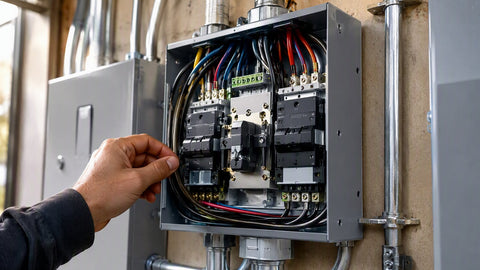
Parallel wiring combines multiple strings at a combiner box, adding currents while keeping voltage constant. This is necessary when your array has more panels than a single string can hold, or when you want to orient strings in different directions (east-west split, for example). Every parallel string needs its own overcurrent protection — NEC 690.9(A) requires a fuse or breaker per source circuit.
| Combiner Configuration | String Fuse | Total Output Current | Homerun Wire | Typical Inverter |
|---|---|---|---|---|
| 2 strings × 10 panels | 15A per string | ~19A (2 × 9.5A) | #8 AWG | 3.8 kW string inverter |
| 3 strings × 10 panels | 15A per string | ~28.5A (3 × 9.5A) | #6 AWG | 5.0 kW string inverter |
| 4 strings × 12 panels | 20A per string | ~46A (4 × 11.5A) | #4 AWG | 8.0 kW string inverter |
| 6 strings × 12 panels | 20A per string | ~69A (6 × 11.5A) | #2 AWG | 12 kW string inverter |
When combining strings of different orientations in one MPPT input, the inverter or controller sees the combined current but the voltage tracks the lowest-Vmp string. If you combine an east-facing string (300V Vmp at 8 AM) with a west-facing string (380V Vmp at 8 AM), the MPPT tracker settles at ~300V and the west string underperforms until afternoon. Better practice: use dual MPPT inputs (most modern inverters have at least two) or separate combiners feeding separate controllers.
MC4 Connectors: The Critical Detail

Getting Your Connections Right in the Field
MC4 connectors are the industry standard for module interconnections, and they are the leading cause of DC arc faults when installed poorly. Here's the field process that keeps callbacks to zero:
- Strip 7–8 mm of insulation. No more, no less. Use a proper stripper, not diagonal cutters — nicked copper creates a hot spot that weakens the crimp.
- Crimp with a Stäubli or Multi-Contact tool. The $15 Amazon crimpers open up after 50 cycles and produce loose joints. A proper tool is $80–$120 and lasts thousands of crimps.
- Tug-test every crimp. 10 lbs of force, no movement. If it slides, cut it and start over.
- Never disconnect under load. MC4s are not load-break rated. Open the string at the combiner first, then disconnect the MC4s. A 400V arc will weld the contacts and damage the housing.
- Check polarity before every click. Reverse polarity on a string inverter blows fuses or damages input diodes. On a charge controller, it can destroy the entire unit. We check polarity at every third panel during installation — catching an error early saves hours.
Last season I replaced an entire string of MC4 jumpers on a commercial array where the installer had used unbranded connectors from an online marketplace. The contact resistance was 3× higher than Stäubli spec, and three connectors had melted to 200°F. Use name-brand connectors — the cost difference is $0.50 per pair versus a $1,200 callback.
| Array Size | String Current (Isc) | Homerun Length | Recommended Wire | Voltage Drop (est.) | Conduit Size |
|---|---|---|---|---|---|
| 2 kW (1 string) | ~9.5A | 50 ft | #10 AWG PV | 1.0% | 1/2" EMT |
| 5 kW (2 strings) | ~19A combined | 75 ft | #8 AWG THHN | 1.2% | 3/4" EMT |
| 8 kW (3 strings) | ~28.5A combined | 100 ft | #6 AWG THHN | 1.3% | 3/4" EMT |
| 10 kW (4 strings) | ~38A combined | 100 ft | #6 AWG THHN | 1.8% | 1" EMT |
| 12 kW (4 strings) | ~46A combined | 150 ft | #4 AWG THHN | 1.4% | 1" EMT |
| 15 kW (5 strings) | ~57A combined | 150 ft | #4 AWG THHN | 1.7% | 1-1/4" EMT |
For the homerun from combiner to inverter, always transition from PV wire to THHN in conduit at the roof edge or combiner location. PV wire is double-insulated for exposure but costs more than THHN; once you're inside conduit, THHN is the economical and code-compliant choice. For ground-mount arrays over 200 feet from the inverter, consider #4 AWG even for smaller arrays — the voltage drop savings often pay for the thicker wire within the first year of production. Browse AWG 6 wire and AWG 4 wire for your project.
Every exposed metal part of the PV system must be bonded to equipment ground per NEC 690.47. This includes module frames, racking, combiner boxes, conduit, and inverter chassis. The equipment ground provides a fault-current path that trips breakers or blows fuses if a live conductor touches metal.
The Final DC Connection at the Inverter
| Ground Type | Conductor | Connection Point | NEC Reference | Purpose |
|---|---|---|---|---|
| Equipment Ground | #6 AWG Cu minimum | All metal enclosures, racking, conduit | 690.47(C) | Safety — fault current path |
| System Ground (DC) | Per inverter/controller spec | One point in DC negative | 690.47(A) | Reference for ungrounded systems |
| Grounding Electrode | #6 AWG Cu to rod | Ground rod or Ufer ground | 250.52, 690.47(D) | Earth reference for fault current |
| Array Ground | #6 AWG Cu or #4 Al | Ground rod at array (if remote) | 690.47(D) | Supplemental electrode for ground-mount |
In ungrounded systems (most modern string inverters), the DC conductors float relative to ground. The equipment ground is the only protection against shock. In negatively grounded battery systems (common with PWM charge controllers), the battery negative is bonded to ground at one point only — usually the charge controller. Multiple neutral-ground bonds create ground loops, which cause corrosion in metallic conduit and erratic controller behavior.
Every new rooftop PV system must have rapid shutdown capability that reduces array voltage to 30V or less within 10 seconds of activation, measured within 10 feet of the array boundary. Two compliant methods dominate the market:
- Module-Level Power Electronics (MLPE): Enphase microinverters or SolarEdge power optimizers shut down each module individually when AC power is lost. Compliance is automatic — no extra wiring, no control boxes. This is the most reliable path; we've had zero rapid-shutdown failures with MLPE in our installed base.
- String-Level Rapid Shutdown Devices (RSD): A transmitter in the inverter or a separate control unit sends a keep-alive signal over the DC conductors. RSD switches at the array cut the strings when the signal stops. The array side drops to 30V; the inverter side retains full string voltage until capacitors discharge. We've replaced four failed RSD units in three years — they are less reliable than MLPE.
For new residential installs, we spec MLPE on every job. The cost premium is $0.10–$0.15/W, but it eliminates rapid-shutdown compliance risk and gives module-level monitoring as a bonus.
Unbox and inspect
Check each module for shipping damage — cracked glass, bent frames, or loose junction boxes. Record serial numbers for warranty registration. Verify that the MC4 leads are long enough for your rail spacing; some manufacturers ship short leads that require extension jumpers.
Mount the first panel and establish grounding
Attach the first module to the rail, install a WEEB clip or lay-in lug on the rail, and run the equipment ground bond wire. It's easier to ground an empty rail than one covered with panels. Torque all rail bolts to spec — loose rails vibrate and damage roof seals.
Connect modules in series
Start at the end farthest from the combiner. Connect the positive MC4 of panel 1 to the negative MC4 of panel 2, and so on. Every third panel, verify string voltage with a multimeter — it should increment by ~40V per panel. A lower reading indicates a bad connection or reversed polarity.
Home-run to combiner
Use #10 AWG PV wire for string homeruns under 100 feet. For longer runs, upsize to #8 AWG to keep voltage drop under 3%. Transition to THHN in EMT below the roof deck. Label every conductor at both ends with string ID and polarity before pulling.
Land in combiner and test
Install string fuses per NEC 690.9, connect positives to the fused busbar and negatives to the negative busbar. Verify open-circuit voltage on every string with a multimeter before closing the output breaker. Strings within 5% voltage of each other are normal; larger variances indicate wiring errors or shaded/damaged panels.
Commission the system
Power up the inverter or charge controller, verify MPPT tracking voltage matches your string Vmp calculation, and record baseline production on a clear day. Set up remote monitoring and hand the homeowner the login credentials, as-built diagram, and warranty paperwork. Schedule the utility inspection if required.
Field takeaway: Draw the single-line diagram before you climb the ladder, size strings for cold-weather Voc, use name-brand MC4 connectors, ground every rail section, and verify polarity at every third panel. The 30 minutes you spend checking voltage during install saves a full day of troubleshooting later. For backup power, pair your array with a hybrid inverter and battery storage from PES.
Can I wire solar panels myself, or do I need an electrician?
Module-to-module wiring and DC homeruns can be done by a competent DIYer, but the AC connection to the main panel, permit submission, and utility inter agreement require a licensed electrician in most jurisdictions. NEC 690 is complex — if you are not comfortable with load calculations, grounding requirements, and rapid shutdown compliance, hire a professional. The permit inspector will catch errors that cost more to fix than the original install.
What happens if I wire panels in parallel instead of series?
Your Solar Wiring Blueprint: Series vs. Parallel
Parallel wiring adds current while keeping voltage constant. At 40V per panel, ten panels in parallel give 40V and 95A — far beyond what most charge controllers or inverters accept. Parallel is appropriate only for low-voltage battery systems (12V or 24V) with PWM controllers, and even then you are limited to 2–3 panels before current becomes unmanageable. For grid-tie and MPPT systems, series is the standard.
How do I know if my MC4 connectors are crimped properly?
A proper crimp shows uniform compression around the copper barrel with no gaps or cracks. The insulation should butt against the crimp barrel with no exposed copper. Do a tug test: pull the conductor with 10 lbs of force — any movement means a bad crimp. Cut it off and redo it. A loose MC4 crimp will heat, oxidize, and eventually arc.
Do solar panels need a separate ground rod?
For roof-mounted arrays, the equipment ground bonds to the premises grounding electrode system — no separate rod needed. For ground-mount arrays, NEC 690.47(D) requires a supplemental ground rod at the array, bonded back to the premises ground with #6 AWG copper. The array rod is supplemental — it does not replace the main grounding electrode.
Can I use extension cords to wire solar panels?
No. Extension cords are not listed for continuous outdoor DC operation, lack UV resistance, and are not rated for 600V. They are a fire hazard and a code violation. Use only listed PV wire (RHW-2) or USE-2 for exposed DC circuits, and THHN/THWN-2 in conduit for protected runs.
What is the maximum number of panels per string?
It depends on the inverter voltage limit and the panel Voc. For a 600V inverter and 60-cell modules with 49V Voc, the practical maximum is 10 panels (490V STC, ~570V cold). For 72-cell modules with 47V Voc, you might fit 11. Always use the manufacturer's string sizing tool and account for record low temperature in your location. When in doubt, reduce by one panel — a slightly shorter string is far better than a fried inverter.
How do I wire panels for a 48V battery bank?
Use three 60-cell panels in series (120V Vmp) for an MPPT charge controller. This gives the controller enough headroom to efficiently down-convert to 48V while staying below the 150V input limit of most controllers. A single panel at 40V into a 48V battery is too low for efficient MPPT and will lose 15–20% of potential harvest. Never connect panels directly to a battery without a charge controller — you will overcharge and damage the battery.
- Solar Panels — 300W to 700W modules
- Charge Controllers — MPPT and PWM for all voltages
- Inverters — string, micro, and hybrid inverters
- Battery Storage — lithium and lead-acid banks
- Circuit Breakers — DC-rated breakers for combiners
- Residential Solar Starter Kits — complete systems
Ready to wire your array? Get a Quote — we'll spec the panels, wire, and balance of system for your project.