440W Mono PERC Bifacial Solar Panel: Specs, String Sizing, and Field Notes
A technical breakdown of the 440-watt half-cut PERC bifacial module class — electrical characteristics, mechanical dimensions, bifacial gain math, and NEC 690.7 / 690.8 design calculations.

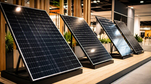
The 440W mono PERC bifacial solar panel sits in one of the most common power classes for residential and light commercial arrays. It is large enough to keep module counts and balance-of-system labor reasonable on a rooftop, and small enough that one installer can still handle it safely. This article is a working technical reference: what the nameplate numbers actually mean, how the dimensions and weight affect racking, how much rear-side (bifacial) energy you can realistically expect, and how to run the NEC 690.7 voltage and 690.8 current calculations that determine strings, conductors, and overcurrent protection. You can browse current inventory in this class in our 440W solar panel collection, the broader bifacial panel category, or the full solar panel catalog.
Each part of the product name describes a measurable design decision, not marketing language:
440W Mono PERC Bifacial Solar Panel: Efficiency and Specifications
Overview of the 440W Monocrystalline Solar Panel
Understanding Mono PERC Technology
- 440W is the rated maximum power (Pmax) at Standard Test Conditions: 1,000 W/m² irradiance, 25 °C cell temperature, and an AM 1.5 spectrum. It is a laboratory rating. Real-world field output is usually 75–85% of nameplate in the middle of a clear day, because cells run hotter than 25 °C and irradiance is rarely a full sun at panel level.
- Mono means monocrystalline silicon — cells sliced from a single continuous crystal ingot. Mono cells hold a consistent efficiency advantage over older polycrystalline technology, which is why poly has effectively disappeared from new module production. See our monocrystalline panel category for the current lineup.
- PERC stands for Passivated Emitter and Rear Cell. A dielectric passivation layer on the back of the cell reflects photons that would otherwise be absorbed as heat in the rear contact back into the silicon for a second chance at conversion, and it reduces rear-surface electron recombination. The practical result is roughly 1% absolute efficiency gain and better low-light and high-temperature behavior than pre-PERC cells. Our PERC panel collection covers this cell architecture across wattage classes.
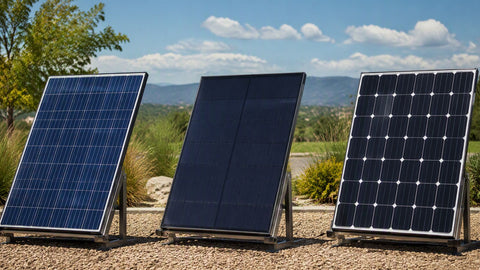
- Bifacial means the module generates power from light hitting both faces. The rear side uses the same PERC cell architecture behind a transparent backsheet or a second pane of glass, so reflected light from the surface behind the array — ground, gravel, white roof membrane, snow — is converted into additional current. The rear side does not add meaningful voltage; it adds current, and that distinction matters for the NEC calculations later in this article.
Most 440W-class bifacial modules are also half-cut designs: 120 half-cells derived from 60 full 182 mm cells, wired so the module behaves electrically like two 60-cell sections in parallel. Half-cutting cuts cell current in half, which reduces resistive (I²R) losses inside the module and improves shade tolerance because bypass diodes cover smaller cell groups. More on that format in the half-cut panel collection.
The table below shows representative STC and NOCT values for a typical 440W 120-half-cell PERC bifacial module (the Aptos DNA-120-BF10-440W class). Always confirm against the specific module datasheet before design sign-off — Voc and temperature coefficients differ slightly between manufacturers, and those differences drive string sizing.
| Parameter | STC (1,000 W/m², 25 °C) | NOCT (~800 W/m², 45 °C) | Notes |
|---|---|---|---|
| Maximum power (Pmax) | 440 W | ≈ 328 W | NOCT output ≈ 74% of nameplate |
| Open-circuit voltage (Voc) | 41.0 V | ≈ 38.2 V | Drives NEC 690.7 max string length |
| Short-circuit current (Isc) | 13.45 A | ≈ 10.9 A | Drives NEC 690.8 conductor sizing |
| Voltage at Pmax (Vmp) | 34.1 V | ≈ 31.5 V | MPPT operating window |
| Current at Pmax (Imp) | 12.90 A | ≈ 10.4 A | 34.1 V × 12.90 A = 440 W ✓ |
| Module efficiency | 20.3% | — | 440 W ÷ 2.165 m² aperture |
| Bifaciality factor (rear/front) | 70% | — | Rear Pmax ≈ 308 W at equal irradiance |
| Max series fuse rating | 25 A | — | Never exceed; see NEC 690.9 |
| Max system voltage | 1,500 V | — | UL 61730 listing |
Two relationships in this table are worth committing to memory. First, Pmax = Vmp × Imp: 34.1 V × 12.90 A = 439.9 W, which rounds to the 440 W nameplate. If a datasheet does not satisfy this identity within rounding error, one of the numbers is wrong. Second, efficiency = Pmax ÷ (aperture area × 1,000 W/m²): this module measures 1.909 m × 1.134 m = 2.165 m², so 440 ÷ 2,165 = 20.3%. Efficiency is not a separate technology claim — it is simply power density restated.
The NOCT column is the honest number for energy modeling. NOCT (Nominal Operating Cell Temperature) conditions — 800 W/m², 20 °C air, 1 m/s wind, open rack — push cell temperature to about 45 °C, and power falls off at the module's temperature coefficient, typically −0.34%/°C for Pmax on PERC product. From 25 °C to 45 °C that is a 6.8% loss on voltage-driven power before irradiance reduction, which is why 328 W at NOCT is a realistic "clear afternoon" expectation, not 440 W.
| Mechanical Parameter | Value (metric) | Value (imperial) | Field relevance |
|---|---|---|---|
| Length | 1,909 mm | 75.2 in | Two-rail portrait layout; rail spans ~1/4 of length |
| Width | 1,134 mm | 44.6 in | Row pitch with ~20 mm inter-module gap |
| Depth (frame) | 30 mm | 1.18 in | Standard clamp zone per manufacturer |
| Weight (glass-glass) | ≈ 32 kg | ≈ 70.5 lb | Two-person lift above shoulder height |
| Front / rear glass | 2.0 mm + 2.0 mm | — | Heat-strengthened; heavier than glass-backsheet |
| Aperture area | 2.165 m² | 23.3 ft² | Efficiency denominator |
| Design load (typical) | 5,400 Pa front / 2,400 Pa rear | ≈ 113 / 50 psf | Confirm against local snow/wind maps |
| Connectors / cable | Stäubli MC4-EVO2, 4 mm² (12 AWG) | — | Mate only with identical connector brand |
At 75 inches long and roughly 70 pounds in glass-glass bifacial construction, this is the largest format one crew member should be carrying solo, and many shops treat it as a two-person lift on ladders and steep pitches. The 2.0 mm + 2.0 mm glass-glass laminate is what makes the bifacial architecture durable — no polymer backsheet to UV-degrade — but it adds about 5 kg over a comparable glass-backsheet module. When you plan staging, figure four modules per trip up a 32-foot ladder as a hard ceiling, and use a ladder hoist above that.
Mounting Options for Bifacial Panels
Racking clamp zones matter more on glass-glass modules than many installers expect. The frameless-laminate-with-frame construction used here requires clamps within the manufacturer's specified zone (typically the inner third of each long rail span) or the design load rating is void. Our solar panel racking systems guide covers rail spacing math, and the racking and mounting category has compatible rail, clamp, and attachment hardware.
Installer note — glass-glass handling
On my first glass-glass bifacial job I treated the modules like the glass-backsheet panels I was used to and stacked them flat on a pallet edge-to-edge. Two modules developed edge chips before we even got them on the roof. Now I keep them vertical in the factory box until the moment of install, use suction handles rated for 50+ kg, and never let a clamp jaw touch glass. The 70-pound weight also changes your ladder rhythm — plan the hoist before the crew is standing on the roof waiting.
Bifacial Gain: Realistic Numbers, Not Brochure Numbers

Bifacial gain is the additional annual energy harvested from the rear face, expressed as a percentage of what the front face alone would produce. It depends on three variables: albedo (ground reflectance), view factor (how much reflected light the rear face actually "sees," which improves with mounting height and row spacing), and the bifaciality factor of the cells (70% for this PERC class, meaning the rear face produces 70% of the front face's power under identical irradiance).
The arithmetic is simple. If the rear face receives irradiance equal to 25% of front irradiance (a decent white roof membrane at 1 m tilt height), rear power = 440 W × 0.25 × 0.70 = 77 W, an instantaneous gain of 17.5%. The table below maps common surfaces to the annual energy gain typically measured in field studies and PVsyst models, with the equivalent instantaneous wattage on the 440 W nameplate:
| Rear surface (albedo) | Typical annual bifacial gain | Equivalent module watts | Application |
|---|---|---|---|
| Dark shingle / soil (0.10–0.15) | 1–5% | 444–462 W | Flush residential rooftop, low tilt |
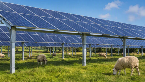
| Grass / green vegetation (0.20–0.25) | 5–8% | 462–475 W | Ground mount, minimal site prep |
| Gravel / gray concrete (0.25–0.35) | 10–15% | 484–506 W | Ground mount or flat commercial roof |
| White TPO / EPDM membrane (0.60–0.80) | 15–20% | 506–528 W | Ballasted flat-roof commercial |
| White geotextile / fresh snow (0.80+) | 20–30% | 528–572 W | Optimized ground mount, winter peaks |
Three honest qualifications. First, flush-mounted residential rooftops see the smallest gains — often 1–3% — because the view factor behind the module is nearly zero; bifacial modules on a comp shingle roof are bought for the glass-glass durability, not the rear harvest. Second, the equivalent watts column is an annualized average, not a rating; inverters and conductors must be sized for the worst-case peak (clear winter day over fresh snow), not the average. Third, rear gain is current gain. Voc does not rise with bifacial illumination in any meaningful way — but Isc and Imp do, which is why NEC 690.8 conductor sizing on bifacial arrays uses an uplift factor.
Installer note — the snow day that sold me on bifacial
We commissioned a 24-module ground mount in January, the morning after a six-inch snowfall, on a day that barely cleared 30 °F. The monitoring showed strings pushing 108% of their front-only modeled output at solar noon — the rear faces were harvesting off a fresh snow field at 0.85 albedo while the cold kept cell voltage high. Annualized, that site lands around 12% gain, but those winter peak days are why I now spec conductor and fuse sizing with the 1.25 bifacial uplift every single time, even when the annual model says I could get away with less.
NEC 690.7 requires that the maximum photovoltaic system voltage — the highest voltage a string can ever produce — not exceed the rating of any connected equipment: the inverter's absolute max input, conductor insulation, and the module's 1,500 V system rating. Crystalline silicon Voc rises as temperature falls, so the code corrects STC Voc for the site's record-low ambient temperature. NEC 690.7(A) offers two methods: the prescriptive correction-factor table (Table 690.7(A) in the 2020 NEC), or a calculated method using the module's Voc temperature coefficient under engineering supervision. The table method is what most residential designers use because it is conservative and needs no special documentation.
Using this module's 41.0 V STC Voc and the crystalline-silicon correction factors:
| Record-low ambient | 690.7(A) factor | Corrected Voc | Max modules @ 600 V | Max @ 1,000 V | Max @ 1,500 V |
|---|---|---|---|---|---|
| 0 °C (32 °F) | 1.10 | 45.10 V | 13 | 22 | 33 |
| −10 °C (14 °F) | 1.14 | 46.74 V | 12 | 21 | 32 |
| −20 °C (−4 °F) | 1.18 | 48.38 V | 12 | 20 | 31 |
| −30 °C (−22 °F) | 1.21 | 49.61 V | 12 | 20 | 30 |
| −40 °C (−40 °F) | 1.25 | 51.25 V | 11 | 19 | 29 |
The math: corrected Voc = 41.0 × 1.14 = 46.74 V at −10 °C, and 600 ÷ 46.74 = 12.84, so a dwelling-unit array (600 V limit per 690.7(B)) maxes at 12 modules per string — you always round down, never up, because 13 × 46.74 = 607.6 V exceeds the limit. On a 1,000 V commercial system the same site allows 21 modules; on a 1,500 V system, 32. Note that the 600 V column flattens between −10 and −30 °C — that is the table-method conservatism. The coefficient method (41.0 V with −0.27%/°C gives 47.1 V at −30 °C instead of 49.6 V) recovers one module in that band, but it requires stamped documentation and an AHJ that accepts it.
The inverter limit usually binds before the code limit does.
Most residential string inverters cap absolute input at 500–600 V and have a narrower MPPT operating window. A 12-module string at 34.1 Vmp runs at about 409 V in operation — comfortably inside a typical 200–500 V MPPT window — but verify both the absolute max (with cold-corrected Voc) and the startup voltage (usually 150–200 V, easily cleared by any string of 6+) against the specific inverter datasheet. See our string inverter category and the inverter selection guide for current options.
NEC 690.8 treats PV current as continuous, and for bifacial modules the design current must account for rear-side boost. The standard calculation chain for this module, using the manufacturer's maximum current uplift of 25% (a common datasheet value for glass-glass PERC bifacial):
| Step | Calculation | Result |
|---|---|---|
| STC short-circuit current (Isc) | From datasheet | 13.45 A |
| Bifacial uplift | 13.45 × 1.25 | 16.81 A |
| Irradiance/continuous factor (690.8) | 16.81 × 1.25 | 21.01 A |
| Minimum conductor ampacity (pre-derate) | ≥ 21.01 A | 12 AWG @ 30 A (90 °C) |
| With rooftop temp/conduit derates | 0.7–0.8 typical combined | Specify 10 AWG (40 A) |
| Max series fuse (module limit) | Datasheet value | 25 A — never exceed |
Check the protection logic: 21.01 A design current is below the 25 A max series fuse, so a single string needs no string fuse under 690.9(C); two parallel strings (42 A fault potential into a faulted string) still stay under... they do not — 2 × 16.81 = 33.6 A available into a fault exceeds the 25 A module rating, so three or more parallel strings require per-string overcurrent protection, and even two strings should be evaluated carefully with bifacial uplift. For the full conductor ampacity tables and derate procedure, see our NEC wire sizing guide, and for disconnect and OCPD selection, the NEC 690 disconnect guide.
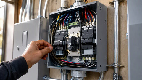
Do not skip grounding and bonding on glass-glass modules: the frame still bonds to the equipment grounding conductor per 690.43, and module-level power electronics or rapid-shutdown devices (690.12) are required on virtually all rooftop systems. Our grounding and bonding guide and NEC compliance overview walk those articles in detail.
Installer note — the string-length mistake I see most
The most common design error I correct on plan reviews is designers using STC Voc for cold climates. A 14-module string of this panel is fine on paper at 41 V (574 V), but at −10 °C it is 654 V — over the 600 V limit and over the input rating of half the residential inverters on the market. The fix costs nothing at design time: pull the ASHRAE extreme minimum for the site, apply the table, and drop to 12 or 13 modules. I have never had an inspector question a string that was too short; I have absolutely failed inspections for strings that were too long.
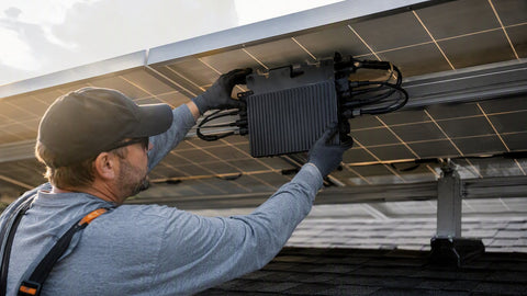
A 440W module in this voltage class (Vmp ≈ 34 V, Imp ≈ 13 A) pairs cleanly with modern string inverters that accept 12–15 A per MPPT input. If your inverter inputs are limited to 12.5 A, you clip a small amount of bifacial peak — acceptable in most annual models, but check the datasheet's max input current per MPPT (not just operating current) before committing, especially on high-albedo sites where Imp can exceed 15 A with rear gain. For shaded or complex roofs, module-level electronics are the better answer: a microinverter or DC optimizer architecture prices out higher per watt but eliminates string-length constraints entirely, because every module operates at its own MPP. Off-grid and hybrid builds using battery coupling should verify charge-controller input windows instead — our MPPT vs PWM explainer covers why an MPPT controller is essentially mandatory at this module voltage.
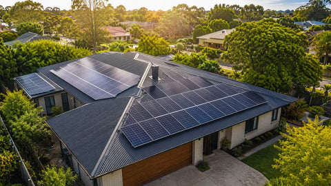
For layout, a 10 kW residential system needs 23 modules (23 × 440 W = 10,120 W DC); 22 comes up 320 W short. On a portrait shingle roof at this module's dimensions, 23 modules occupy roughly 560 ft² of roof including walkways and setbacks — run your roof square footage through the solar system size calculator and cross-check inverter loading with the inverter sizing calculator. Keep DC-to-AC ratio between 1.15 and 1.30 for most climates; bifacial ground mounts on high-albedo surfaces should stay at the lower end of that band because the rear gain eats into the clipping headroom you were counting on.
How much power does a 440W bifacial panel actually produce per day?
A 440W panel in a location averaging 5 peak sun hours produces about 440 W × 5 h × 0.80 (system derate) ≈ 1.76 kWh per day from the front face. A bifacial ground mount over gravel adds roughly 10–15%, putting daily production near 1.95–2.0 kWh. Flush-mounted on a dark shingle roof, rear gain is typically only 1–3%.
What is the difference between PERC and standard monocrystalline cells?
Performance and Efficiency
PERC adds a passivation layer on the rear of the cell that reflects unabsorbed light back into the silicon and reduces electron recombination. The measurable result is about 1% absolute efficiency gain, better high-temperature performance, and improved low-light response compared with pre-PERC (Al-BSF) cells, which have largely exited the market.
How many 440W panels do I need for a 10 kW system?
23 panels: 23 × 440 W = 10,120 W. Twenty-two panels yield only 9,680 W, which falls short of a 10 kW DC design target. The array occupies about 560 ft² of roof area including required setbacks.
Do bifacial panels make sense on a regular shingle roof?
Marginal at best. Rear-side gain depends on reflected light reaching the back of the module, and a flush mount over dark shingles provides almost none — typically 1–3% annually. The glass-glass construction is still worth buying for durability and fire rating, but the economics of bifacial gain favor ground mounts, carports, and white-membrane flat roofs with meaningful standoff height.
How cold does it have to be before cold-weather Voc actually limits my string?
At 0 °C the 690.7(A) correction is 1.10 (45.1 V per module), which still allows 13 modules on a 600 V system. At −10 °C the factor rises to 1.14 and the limit drops to 12. If your site's record low is −15 °C or colder, run the calculation before finalizing any string over 11 modules on a residential 600 V system.