Hooking solar panels to batteries is the project that separates people who read manuals from people who buy replacement charge controllers. The concept is simple — panels feed a controller, the controller feeds a battery bank, an inverter turns stored DC into household AC. The details are where systems live or die: wire gauge, fuse placement, charge voltage setpoints, and the order in which you connect things. We've helped thousands of off-grid and backup builds through the equipment side, and the failures are always the same handful of mistakes. This guide walks the full build the way we'd spec it across the counter, with the NEC references and the math included.
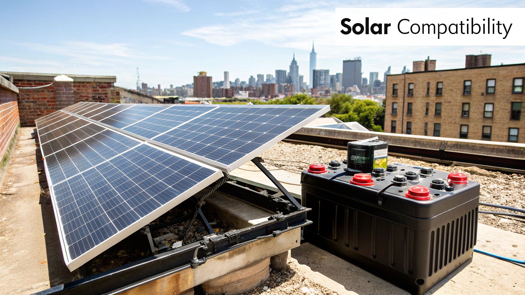
Safety up front: battery banks store enough energy to weld a dropped wrench to a terminal, and PV strings at 400V DC do not forgive. If any step here exceeds your comfort with electrical work, that step is where you hire a licensed electrician. The solar installation guide and battery installation guide cover the broader system context.
Understanding Your Core Solar Components
The Four Pillars of Your System
Every solar-plus-storage system, cabin-scale to whole-home, has the same four organs: the array (panels), the charge controller (the brain that protects the batteries), the battery bank (the tank), and the inverter (the translator to AC). Undersize any one and the others can't compensate — a giant array on a small controller clips production, a huge bank on a small array never charges fully in winter, and a small inverter trips while the batteries sit full.
Essential Components and Their Functions
| Component | Primary Function | Key Specification to Check | Example Brands We Stock |
|---|---|---|---|
| Solar panels | Convert sunlight to DC power | Wattage, Voc (for controller input limits), temperature coefficient | JA Solar, Trina, REC |
| Charge controller (MPPT) | Regulates array output into proper battery charging; prevents overcharge | Max input voltage, max charge current, battery chemistry profiles | Victron, MidNite, Morningstar |
| Battery bank | Stores energy for night and cloudy days | Usable kWh, chemistry (LiFePO4 vs AGM), cycle life, BMS quality | EG4, Fortress, SimpliPhi, Trojan |
| Inverter (or inverter/charger) | Converts battery DC to 120/240V AC | Continuous + surge watts, waveform (pure sine only), idle draw | Sol-Ark, EG4, OutBack, Magnum |
Sizing Your System for Real-World Demands
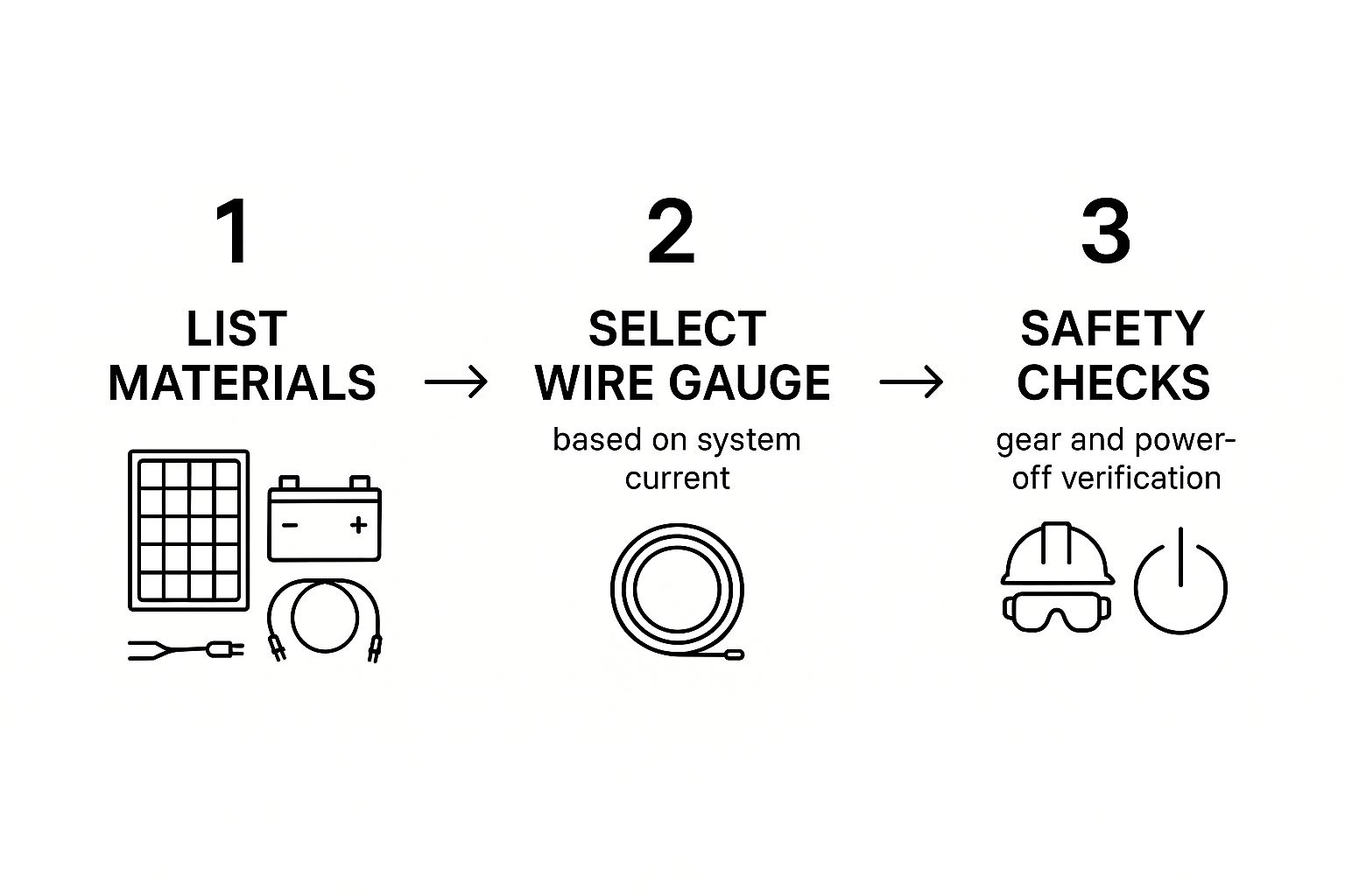
Calculating Your Battery Needs
Battery sizing starts from the load list, not the panel count. Tally daily consumption in kWh (the full method is in our power consumption guide), decide days of autonomy — 1 day for grid-tied backup, 2–3 days for off-grid — then divide by usable depth of discharge. LiFePO4 delivers 90–95% of nameplate routinely; AGM and flooded lead-acid should be planned at 50% to preserve cycle life. Worked example: a cabin using 5 kWh/day with 2 days of autonomy on LiFePO4 needs 5 × 2 ÷ 0.9 ≈ 11.1 kWh — a 48V, 230Ah bank, which in practice means two 10 kWh-class rack modules or three 48V 100Ah units. The same load on AGM needs 20 kWh of nameplate — double the footprint, double the weight, and a shorter service life, which is why LiFePO4 has taken over the market.
| Daily Load | Autonomy | Chemistry | Required Nameplate Capacity | Typical Configuration |
|---|---|---|---|---|
| 2 kWh (weekend cabin) | 2 days | LiFePO4 | ~4.5 kWh | One 48V 100Ah module or a 5 kWh unit |
| 5 kWh (full-time off-grid cabin) | 2 days | LiFePO4 | ~11 kWh | Two 10 kWh-class modules |
| 10 kWh (efficient home) | 1.5 days | LiFePO4 | ~17 kWh | Three to four rack modules; 15–30 kWh systems |
| 10 kWh (efficient home) | 1.5 days | AGM | ~30 kWh | Large, heavy, rarely sensible in 2026 — shown for contrast |
| 20 kWh (all-electric home backup) | 1 day | LiFePO4 | ~22 kWh | Whole-home systems: 20 kWh+ batteries |
Matching Solar Panels to Your Battery Bank
The array must refill the bank on an average day, with margin. The field rule: array watts ≈ daily Wh ÷ local peak sun hours × 1.2 (loss factor for heat, wiring, controller efficiency). For 5 kWh/day in a 3.5-peak-sun-hour climate: 5,000 ÷ 3.5 × 1.2 ≈ 1,715W — call it 2 kW, which is five 400W panels. Undersizing the array is the most common off-grid failure mode we see; a battery that never reaches 100% state of charge sulfates (lead-acid) or drifts out of balance (lithium without a full charge to trigger BMS balancing), and both die young. When in doubt, add a panel — modules are the cheapest component in the system.
Wiring Your Solar Panels and Charge Controller
Series vs. Parallel Wiring Explained
Series wiring adds voltage, keeps current constant: two 40V/11A panels in series make 80V/11A. Parallel wiring adds current, keeps voltage constant: the same two in parallel make 40V/22A. Series strings are the default for MPPT systems because higher voltage means smaller wire and less loss over distance — but string voltage has a hard ceiling: your controller's maximum input voltage, checked at the coldest recorded local temperature, because Voc rises as temperature drops. A string reading 380V on a mild day can push 430V+ in a hard freeze and cook a 450V-rated controller. Always run the cold-temperature Voc math before landing the wires.
| Configuration | Result | When to Use It | Watch Out For |
|---|---|---|---|
| Series (string) | Voltages add, current constant | MPPT controllers, long wire runs, most residential arrays | Cold-weather Voc ceiling; one shaded panel drags the string |
| Parallel | Currents add, voltage constant | PWM systems, small 12/24V arrays, mixed-orientation panels | Thicker wire required; fusing per string above 2 strings |
| Series-parallel | Both scale in blocks | Larger arrays on high-voltage MPPT controllers | Match string lengths exactly; fuse each parallel string |
An NEC-Compliant Checklist for Professionals
The code articles that govern this build: NEC 690 (PV systems — wiring methods, disconnects, rapid shutdown where required, grounding), NEC 706 (energy storage systems — the home of battery-specific rules), NEC 480 (storage batteries), NEC 240 (overcurrent protection — fuse and breaker sizing), NEC 250 (grounding and bonding), and NEC 310.16 (conductor ampacity). The non-negotiables we check on every build: a listed disconnect within sight of the battery bank, overcurrent protection on every ungrounded conductor leaving the battery (fuses at the battery end of the cable run, not the inverter end), conductors sized at 125% of maximum continuous current, and proper labeling at every disconnect and junction. Our NEC compliance guide expands each article.
Connecting The Battery Bank and Inverter Safely
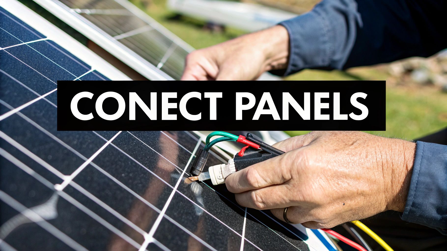
Cable Sizing and Overcurrent Protection
Battery-to-inverter cable is where DIY builds most often go wrong, because 12V systems pull astonishing current: a 2,000W inverter at 12V draws ~167A continuous, which after the 125% NEC factor means a 208A-rated conductor and fuse — 4/0 copper territory. The same inverter at 48V draws 42A and runs happily on 6 AWG. This is the single best argument for 48V battery banks on anything above 1,500W of inverter.
Wire Gauge and Fuse Sizing Reference
| System Amperage (Amps) | Recommended Wire Gauge (AWG, Cu, 75°C per NEC 310.16) | Required Fuse/Breaker Size (NEC 240.6 standard) |
|---|---|---|
| Up to 28A continuous | 8 AWG | 40A |
| Up to 40A continuous | 6 AWG | 50A |
| Up to 52A continuous | 4 AWG | 65–70A |
| Up to 68A continuous | 2 AWG | 85–90A |
| Up to 92A continuous | 1/0 AWG | 110–125A |
| Up to 120A continuous | 2/0 AWG | 150A |
| Up to 160A continuous | 4/0 AWG | 200A |
Fuse types matter: use Class T fuses for lithium battery banks — their interrupt rating (up to 200,000A) is what actually stops a dead short across a LiFePO4 bank, where ANL and Mega fuses can arc over and fail to clear. Class T holders and fuses are in our fuses section, and proper lugs, heat shrink, and battery cable are under wire & cable.
Final Connections and Terminal Torque
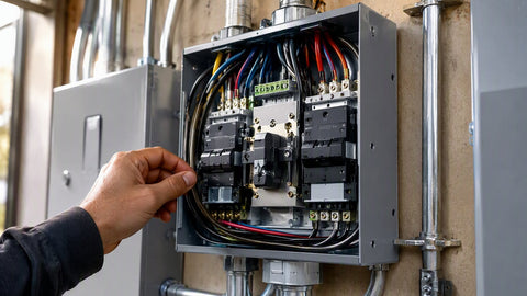
The connection order is a safety sequence, not a suggestion: battery bank fully assembled and fused → charge controller connected to the battery FIRST (so it boots and detects system voltage) → then PV array to controller → then inverter to battery via its own fuse and disconnect → AC loads last. Reverse order on shutdown. Torque battery terminals to the manufacturer spec — typically 8–12 N·m (roughly 70–105 in-lb) on M8 rack-battery terminals, marked on quality equipment — with a calibrated torque wrench, not a calibrated wrist. I've seen a loose battery lug heat to the point of melting its terminal insulator on a 100A load; the resistance of a sloppy connection turns amperage into a space heater. After the first week of operation, re-torque everything once; copper creeps.
Commissioning Your System and Avoiding Common Pitfalls
Programming Your Charge Controller
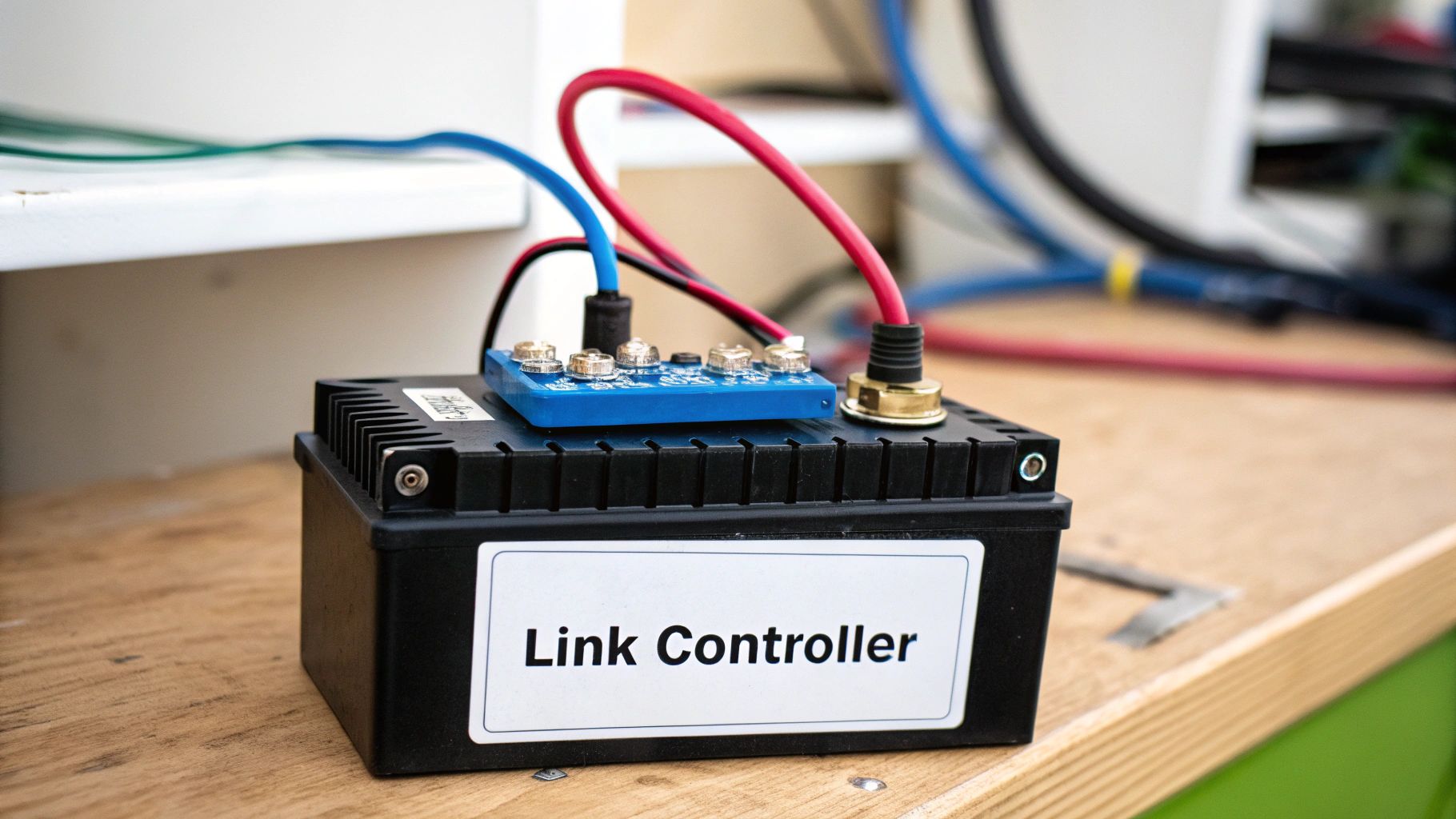
Charge parameters must match the battery manufacturer's datasheet, not generic defaults. Typical 48V (51.2V nominal) LiFePO4 setpoints: absorption/bulk 56.0–56.8V, float 54.0–54.4V (or float disabled), temperature compensation OFF for lithium, equalization NEVER. AGM: absorption 57.6V, float 55.2V, temp compensation enabled. Flooded: similar to AGM with monthly equalization per the battery maker. Wrong setpoints are silent killers — chronic undercharge unbalances lithium banks; overcharge vents and ages lead-acid. Victron's SmartSolar MPPT line and MidNite controllers like the MNEMS4448 make this a five-minute menu job with per-chemistry presets; verify the preset values against your battery datasheet anyway.
Choosing Your System Voltage: 12V, 24V, or 48V
System voltage is the first design decision and the one that's painful to change later. The physics are simple: for the same power, doubling voltage halves current, and current is what sizes your wire, fuses, and controller cost. A 12V bank suits RVs, vans, and small marine systems up to about 1,000W of inverter — beyond that, the amperage demands cable thick as your thumb. A 24V bank stretches to roughly 2,000W and remains common in boats and legacy RVs. A 48V bank is the modern default for cabins and homes: a 5,000W inverter draws a manageable ~104A, charge controllers push twice the array watts through the same amp rating (a 60A controller manages 3.4 kW of array at 48V versus 850W at 12V), and the rack-battery ecosystem — 48V batteries, hybrid inverters, pre-wired power centers — is built around it. If you're building anything meant to power a dwelling, start at 48V. Nobody has ever messaged us wishing they'd chosen a lower system voltage.
MPPT vs. PWM: The Controller Decision
PWM controllers are switches that connect the array to the battery directly — cheap, durable, and wasteful, because a 36V-array on a 12V battery through PWM discards the voltage difference as unused potential, throwing away 30%+ of the array's capability. MPPT controllers are DC-DC converters that track the array's maximum power point and transform excess voltage into additional charging current — routinely harvesting 20–30% more energy than PWM from identical panels, and enabling high-voltage strings with thin wire. The rule in 2026 is simple: PWM survives only in tiny systems (a single panel on a gate opener or boat); anything with 400W+ of array earns back the MPPT price difference within the first year of recovered energy. Our charge controller catalog spans both, and the MPPT vs. PWM deep dive runs the numbers side by side. For mid-size banks, 60A-class units (60A controllers) cover most cabin builds; whole-home arrays step up to 100A units or multiple controllers.
Grounding and Bonding: The Unsexy Safety Layer
Every metal chassis — panel frames, racking, controller, inverter case — bonds to a common equipment grounding system, and the system gets one (and only one) ground reference point per NEC 250. Panel frames ground through listed racking hardware (integrated bonding clamps and lugs from lines like IronRidge and Unirac), not sheet-metal screws into aluminum. The battery negative or positive bond depends on system design — most modern 48V equipment expects a negative-ground architecture — and mixing grounding philosophies between components creates the kind of fault current paths that damage equipment in ways warranties don't cover. When in doubt, follow the inverter manufacturer's grounding diagram exactly; they wrote it to satisfy both the NEC and their own protection circuitry. Our grounding and bonding guide walks the full detail.
Maintenance: Keeping the System Alive for Decades
Solar-plus-storage is low-maintenance, not no-maintenance. Monthly: glance at the controller's harvest numbers against your baseline — a 20% unexplained drop means shading, soiling, or a failing string. Quarterly: check terminal torque on the battery bank's main connections (thermal cycling loosens lugs), inspect cable jackets for chafe where they pass through conduit, and verify the enclosure vents are clear. Annually: wash the array (soiling costs 3–7% in dusty regions, more near gravel roads), exercise every disconnect so it doesn't seize, and review battery state-of-health through the BMS data. Flooded lead-acid adds monthly electrolyte checks with distilled water only. Lithium banks mostly ask to be kept between 32°F and 113°F and charged fully often enough for the BMS to balance — once a week minimum, and daily in normal service. The battery life extension guide has the full maintenance calendar.
Hybrid Inverter/Chargers: The Modern Shortcut
Everything described above as four separate boxes increasingly ships as one: hybrid inverter/chargers combine the MPPT controller, battery charger, inverter, and automatic transfer switch in a single UL-listed unit. A Sol-Ark or EG4-class hybrid (see hybrid inverters and pre-wired inverter packages) takes the array on its PV inputs, the battery on its DC terminals, the grid or generator on its AC input, and the loads on its output — with the changeover logic, charge programming, and monitoring already integrated. For whole-home backup this is now the default architecture: fewer boxes, fewer cable runs, one warranty conversation. The trade-off is a single point of failure and a higher ticket; for cabins and modular builds, discrete components still make sense because you can replace the controller without replacing the inverter.
Cold-Weather and Hot-Weather Notes
Temperature cuts both ways in this system. Cold boosts PV output (panels love clear, freezing days) but freezes lithium charging — LiFePO4 cells must not be charged below 32°F/0°C, which is why quality batteries carry low-temperature charge cutoffs and why rack batteries belong indoors or in heated enclosures. If the bank must live in an unheated space, heated battery boxes or self-heating battery models solve it; skipping that detail is how people kill a $4,000 bank in one January night. Heat is the quieter enemy: battery cycle life roughly halves for every 15°F above 77°F sustained, and charge controllers derate in hot enclosures. Ventilate the battery room, shade the inverter, and give every box its clearance specs — the manuals' installation diagrams exist because the thermal testing did.
The Commissioning Sequence
First power-up checklist, in order: verify polarity with a meter before touching any terminal (reversed polarity on a charge controller is usually fatal to the controller). Confirm bank voltage reads as expected. Connect the controller to the battery; confirm it boots and reads the correct system voltage. Program the charge profile. Land the PV array with the string disconnect open, verify string Voc against the cold-weather calculation, then close the disconnect in full sun and watch the controller sweep to charging. Connect the inverter, test with a small resistive load first (a lamp, not the well pump), then step up. Log baseline numbers: charge voltage achieved, array watts at solar noon, inverter output under load. Those baselines turn every future troubleshooting session into a comparison instead of a guessing game.
The Pitfalls We See Most
Mixed battery ages or chemistries in one bank — never parallel a new battery with a two-year-old one; the weak unit drags the strong one down to its level. Missing battery-end fuses, because "the inverter has a breaker" — the cable between battery and inverter is the unfused fire path. Undersized arrays that never finish a charge cycle. Controllers programmed to "lithium" while connected to AGM. And my personal repeat offender: MC4 connectors crimped with pliers instead of a proper crimper, which work loose and arc. Every one of these is free to avoid and expensive to learn.
Two more that deserve naming. Voltage drop denial: long 12V runs sized by ampacity tables but not by voltage drop arrive at the inverter sagging under load, and the inverter alarms or shuts down at the worst moment — for runs over 10 feet at 12V or 24V, calculate drop (V = 2 × length × current × resistance per foot) and upsize until drop stays under 3%. And documentation amnesia: label every cable at both ends the day you install it. Three years later, when you're adding a second inverter at midnight, the labeled system is a joy and the unlabeled one is a trace-every-wire-with-a-toner weekend.